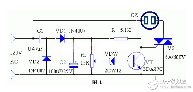
If the grid voltage suddenly rises and exceeds 250V, the voltage at the midpoint of RP will cause VDW to break down and conduct. After VDW conducts, the transistor VT is turned on. After VT conducts, the voltage drop between the collector and the emitter is very small, which is not enough to trigger VS, causing VS to cut off. Therefore, the home appliances in the socket XS are powered off and stop working, thus achieving the purpose of protection. Once the grid voltage drops, VT is cut off again, and the collector potential of VT increases, triggering VS to conduct, and the home appliances are powered on and continue to work.
Component Selection
R resistor 5.1K1, RP potentiometer 15K choose multi-turn precision potentiometer1, C1 metallized paper dielectric capacitor 0.47uF withstand voltage ≥400V1, C2 electrolytic capacitor 100uF/25V1, VD1, 2 rectifier diode IN40072, VDW voltage regulator diode 12V 2CW121, VT crystal transistor 3DA87C, 3DG12, etc.1, VS bidirectional thyristor 6-10A withstand voltage ≥600V1, CZ power socket 10A 250V1
The debugging of the device is very simple. When the grid voltage is 220V, adjust RP so that VDW does not break down. When the voltage rises to 250V, VT is saturated and turned on. It is more convenient to use a voltage regulating transformer to simulate the changes of the mains during debugging.
Previous article:Single-phase auxiliary electricity meter circuit design for smart home appliances
Next article:Detailed explanation of PC intelligent home appliance control system circuit design
Recommended ReadingLatest update time:2024-11-16 13:53

- Popular Resources
- Popular amplifiers
- MathWorks and NXP Collaborate to Launch Model-Based Design Toolbox for Battery Management Systems
- STMicroelectronics' advanced galvanically isolated gate driver STGAP3S provides flexible protection for IGBTs and SiC MOSFETs
- New diaphragm-free solid-state lithium battery technology is launched: the distance between the positive and negative electrodes is less than 0.000001 meters
- [“Source” Observe the Autumn Series] Application and testing of the next generation of semiconductor gallium oxide device photodetectors
- 采用自主设计封装,绝缘电阻显著提高!ROHM开发出更高电压xEV系统的SiC肖特基势垒二极管
- Will GaN replace SiC? PI's disruptive 1700V InnoMux2 is here to demonstrate
- From Isolation to the Third and a Half Generation: Understanding Naxinwei's Gate Driver IC in One Article
- The appeal of 48 V technology: importance, benefits and key factors in system-level applications
- Important breakthrough in recycling of used lithium-ion batteries
- Innolux's intelligent steer-by-wire solution makes cars smarter and safer
- 8051 MCU - Parity Check
- How to efficiently balance the sensitivity of tactile sensing interfaces
- What should I do if the servo motor shakes? What causes the servo motor to shake quickly?
- 【Brushless Motor】Analysis of three-phase BLDC motor and sharing of two popular development boards
- Midea Industrial Technology's subsidiaries Clou Electronics and Hekang New Energy jointly appeared at the Munich Battery Energy Storage Exhibition and Solar Energy Exhibition
- Guoxin Sichen | Application of ferroelectric memory PB85RS2MC in power battery management, with a capacity of 2M
- Analysis of common faults of frequency converter
- In a head-on competition with Qualcomm, what kind of cockpit products has Intel come up with?
- Dalian Rongke's all-vanadium liquid flow battery energy storage equipment industrialization project has entered the sprint stage before production
- Allegro MicroSystems Introduces Advanced Magnetic and Inductive Position Sensing Solutions at Electronica 2024
- Car key in the left hand, liveness detection radar in the right hand, UWB is imperative for cars!
- After a decade of rapid development, domestic CIS has entered the market
- Aegis Dagger Battery + Thor EM-i Super Hybrid, Geely New Energy has thrown out two "king bombs"
- A brief discussion on functional safety - fault, error, and failure
- In the smart car 2.0 cycle, these core industry chains are facing major opportunities!
- The United States and Japan are developing new batteries. CATL faces challenges? How should China's new energy battery industry respond?
- Murata launches high-precision 6-axis inertial sensor for automobiles
- Ford patents pre-charge alarm to help save costs and respond to emergencies
- New real-time microcontroller system from Texas Instruments enables smarter processing in automotive and industrial applications
- Error message when importing bsp project into CCS6
- Many people like to use S9013 as a driver for buzzers, small fans, and LEDs. What is the advantage of S9013 over S8050? High frequency...
- GB21437.2 Pulse 1 Standard Questions
- Nanosecond Laser Driver Reference Design for LiDAR
- Must-read before joining the group: Proposal for the Switching Power Supply Study Group!
- The best textbook for getting started with ADS (teaching you 9 experiments step by step)
- 【ST NUCLEO-G071RB Review】_06_DHT11 Temperature and Humidity Sensor Experiment
- BMW's new car uses electronic ink technology to change color with one click. Do you like it?
- Power supply temperature drift and ripple issues of constant current source
- How to enable TI 15.4-Stack to support 470M frequency band

 【Follow me Season 2 Episode 1】-Mission Code (Adafruit Circuit Playground Express Development Board)
 Multi-port and shared memory architecture for high-performance ADAS SoCs
 【Follow me Season 2 Episode 1】Source code


 京公网安备 11010802033920号