Based on the characteristics of LED , the radiant light energy of LED depends entirely on the driving current and junction temperature. Therefore, a good thermal management system is a prerequisite for LED applications to perform well. In the field of automotive light-guide daytime running lights, due to the constraints of the tiny light source space size and the less efficient optical system, high-power LEDs must be used, resulting in heat concentration. Therefore, a good thermal management solution must be adopted in the light-guide daytime running light application.
This paper uses OSRAM Opto Semiconductors QFN package LED KWH2L531.TE as the light source and considers a high-performance thermal management system. The thermal performance of various PCBs is compared, the influence of the heat sink is analyzed, and the importance of PCB material selection and heat sink design is emphasized.
Introduction of Light Guide Daytime Running Lights
A light guide is a light-guiding device based on the principle of total reflection of light. When light is transmitted from a denser medium to a less dense medium, according to Snell's law and the law of total reflection, when the incident angle is greater than the critical angle, the light will not be emitted from the denser medium to the less dense medium, but will be totally reflected at the boundary between the two media. Therefore, when light is transmitted in a light guide (dense medium) at an angle greater than the critical angle, total reflection occurs, causing the light to continuously transmit forward in the light guide. If some corrugations or sawtooth structures are made on the surface of the light guide, the total reflection conditions of the light are destroyed, causing part of the light to escape from the light guide. By adjusting the corrugations and sawtooths, a uniform brightness distribution on the surface of the light guide can be achieved. Since the efficiency of the light guide is lower than that of the reflector and lens, the efficiency varies depending on the shape of the light guide. To achieve the minimum DRL requirement of 400cd of ECE R87, a light guide usually requires a luminous flux of about 500lm. According to the current efficiency of LEDs, at least two chips are required to achieve this. Since the diameter of the light guide is usually only 6mm to 8mm, the size of the LED particles is very high. At present, all major LED manufacturers have released small-size packages (Figure 1). At a current of 700mA, each chip can reach about 200lm; therefore, two separate LED particles are usually required and the current can only be increased to achieve this;
OSRAM Opto Semiconductors' latest QFN packaged LED KWH2L531.TE (Figure 2) has a single rated power of 6.5W, a maximum drive current of 1.2A, a maximum operating junction temperature of 150℃, and can reach 175℃ for a short time. Therefore, it is particularly suitable for forward lights with high temperature requirements. The two chips of this LED are packaged together, and the chip spacing is only 0.1mm. Compared with the method of using two separate LEDs, the spacing is greatly reduced, which can improve the coupling efficiency of the light guide. At present, KWH2L531.TE can reach 560lm under the conditions of a drive current of 1A and 25℃; even considering the light decay, one LED can achieve the requirements of a single light guide daytime running light, but because the chips are relatively concentrated, heat accumulates, so the heat dissipation performance of the entire system is required to be high. Taking OSRAM KWH2L531.TE LED as an example, this article focuses on the heat dissipation perspective, analyzes and compares the performance of the entire heat dissipation system, and gives appropriate suggestions for the heat dissipation system of the light guide DRL.
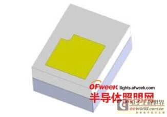
Figure 1 LUW CEUP

Figure 2 KWH2L531.TE
Analysis of the cooling system of the light-guide type daytime running lights Analysis of the cooling system of the light-guide type daytime running lights
The KWH2L531.TE LED light guide daytime running light system (as shown in Figure 3) includes optical devices (light guides), LEDs and heat dissipation devices (Figure 4).
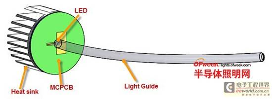
Figure 3 Light-guided daytime running light system
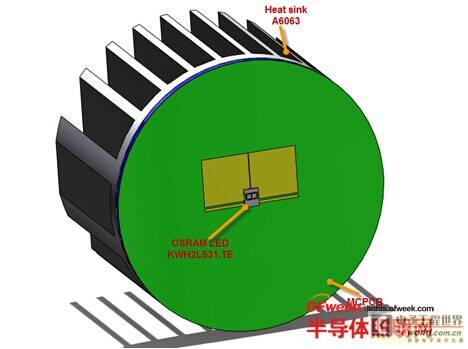
Figure 4 Daytime running light cooling system
Therefore, PCB and radiator will be the main factors affecting the entire cooling system. In order to simplify the analysis and obtain a more intuitive comparison, PCB and radiator will be analyzed and compared separately.
Factors to consider in heat dissipation design of light-guide daytime running lights
1) PCB design
For an LED with high heat flux density and single power consumption of 6.5W, it is necessary to choose a PCB with a metal substrate. There are two types of metal substrate PCBs on the market, namely aluminum substrates and copper substrates, but based on cost and actual LED heat considerations, copper substrates are not used in this paper. Aluminum substrates are usually composed of three layers (as shown in Figure 5): a conductive layer (copper), an insulating layer (epoxy mixed thermal conductive material) and a substrate aluminum layer.
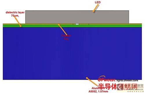
Figure 5 Aluminum substrate
Among the entire PCB material composition, the thermal conductivity of the insulation layer is usually much lower than that of aluminum and copper, generally between 0.35w/mk and 3.0w/mk. Therefore, the thermal conductivity of the insulation layer material directly determines the performance of the entire PCB, and usually also directly determines the price of the PCB board.
As shown in Figure 6, the PCB is analyzed independently, the copper thickness is set to 35um, the back of the PCB is set to a constant temperature of 25℃ and given infinite convection, and only heat conduction is considered . The LED thermal power consumption is 5.2W. Three typical PCB materials (Figure 7) are selected for analysis, and the results (Figure 8) are obtained.
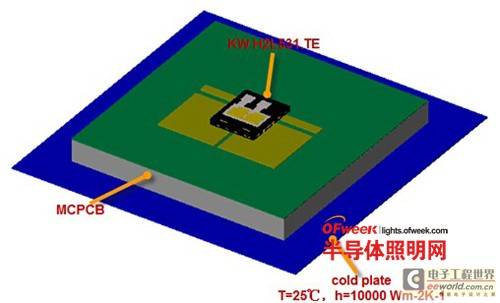
Figure 6 PCB analysis settings
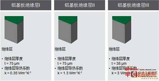
Figure 7 Comparison of performance of three different PCB insulation layers

Figure 8 Comparison of temperature distribution and thermal resistance of three different insulation layers
As shown in Figure 8, the thermal resistance of a PCB with a thermal conductivity of 0.35W/mk and a thickness of 75um is nearly 8K/W higher than that of a PCB with a thermal conductivity of 3.0W/mk and a thickness of 38um, causing a temperature rise of 43℃. From Figure 9, it can be clearly seen that this is enough to cause a difference of more than 10% in the light decay of the two, and even color drift. Generally speaking, a high thermal conductivity and thin thickness of the insulation layer can greatly reduce the thermal resistance of the PCB, but the price will also increase exponentially. Therefore, for the LED KWH2L531.TE, if there is a limit on the size of the heat sink space or a high luminous flux requirement, a high-performance PCB is usually required. If you want to balance price and performance, it is generally recommended to use an aluminum substrate with an insulation layer thermal conductivity of about 2.0W/mk and a thickness of 75um.
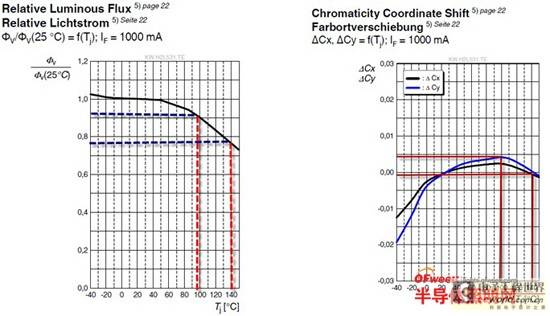
Figure 9 KWH2L531.TE luminous flux and color change curve with temperature
2) Radiator design
There are usually two methods for designing light-guide daytime running light radiators: external radiator and internal radiator. This paper is based on Figure 3, an aluminum extruded radiator with a diameter of 55mm and a fin height of 35mm, and a PCB with a thermal conductivity of 2.2W/mk and an insulation layer thickness of 75um. The two methods are compared and analyzed.
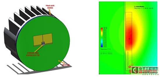
Figure 10 Radiator external temperature distribution

Figure 11 Temperature distribution inside the heat sink
From Figure 10 and Figure 11, we can see that based on the same heat sink size and PCB performance, when the heat sink is external, RthJA (junction to ambient thermal resistance) is 10.7K/W, and the LED junction temperature is 106℃; when the heat sink is internal, RthJA is 15.1K/W, and the LED junction temperature is 125℃. Therefore, the thermal resistance difference caused by the shell reaches 4.4K/W, and the junction temperature difference is 19℃. Therefore, in the actual heat dissipation system design, if the heat sink can be external, it can be made relatively small or a lower-cost PCB can be selected to achieve the same junction temperature and luminous flux.
Taking all the above factors into consideration, the performance of the PCB board and the design of the heat sink directly affect the performance of the LED.
Summarize
This article mainly introduces the heat dissipation design of OSRAM KWH2L531.TE LED light guide DRL and analyzes and discusses the two main factors that affect the heat dissipation design, PCB material selection and heat sink design. According to the space that the light guide DRL can provide in actual application, choosing the appropriate PCB and heat sink placement method can make the LED perform efficiently.
Previous article:Summary of classic circuits for secondary constant current of LED power supply
Next article:Application research of RGB car atmosphere light based on temperature feedback control
- MathWorks and NXP Collaborate to Launch Model-Based Design Toolbox for Battery Management Systems
- STMicroelectronics' advanced galvanically isolated gate driver STGAP3S provides flexible protection for IGBTs and SiC MOSFETs
- New diaphragm-free solid-state lithium battery technology is launched: the distance between the positive and negative electrodes is less than 0.000001 meters
- [“Source” Observe the Autumn Series] Application and testing of the next generation of semiconductor gallium oxide device photodetectors
- 采用自主设计封装,绝缘电阻显著提高!ROHM开发出更高电压xEV系统的SiC肖特基势垒二极管
- Will GaN replace SiC? PI's disruptive 1700V InnoMux2 is here to demonstrate
- From Isolation to the Third and a Half Generation: Understanding Naxinwei's Gate Driver IC in One Article
- The appeal of 48 V technology: importance, benefits and key factors in system-level applications
- Important breakthrough in recycling of used lithium-ion batteries
- Innolux's intelligent steer-by-wire solution makes cars smarter and safer
- 8051 MCU - Parity Check
- How to efficiently balance the sensitivity of tactile sensing interfaces
- What should I do if the servo motor shakes? What causes the servo motor to shake quickly?
- 【Brushless Motor】Analysis of three-phase BLDC motor and sharing of two popular development boards
- Midea Industrial Technology's subsidiaries Clou Electronics and Hekang New Energy jointly appeared at the Munich Battery Energy Storage Exhibition and Solar Energy Exhibition
- Guoxin Sichen | Application of ferroelectric memory PB85RS2MC in power battery management, with a capacity of 2M
- Analysis of common faults of frequency converter
- In a head-on competition with Qualcomm, what kind of cockpit products has Intel come up with?
- Dalian Rongke's all-vanadium liquid flow battery energy storage equipment industrialization project has entered the sprint stage before production
- Allegro MicroSystems Introduces Advanced Magnetic and Inductive Position Sensing Solutions at Electronica 2024
- Car key in the left hand, liveness detection radar in the right hand, UWB is imperative for cars!
- After a decade of rapid development, domestic CIS has entered the market
- Aegis Dagger Battery + Thor EM-i Super Hybrid, Geely New Energy has thrown out two "king bombs"
- A brief discussion on functional safety - fault, error, and failure
- In the smart car 2.0 cycle, these core industry chains are facing major opportunities!
- The United States and Japan are developing new batteries. CATL faces challenges? How should China's new energy battery industry respond?
- Murata launches high-precision 6-axis inertial sensor for automobiles
- Ford patents pre-charge alarm to help save costs and respond to emergencies
- New real-time microcontroller system from Texas Instruments enables smarter processing in automotive and industrial applications
- Double 12 limited time offer | Tektronix year-end rewards, oscilloscope third-order upgrade!
- Driver chip in Type-c OTG mode - LDR6028S
- The pressure sensor outputs the pressure value in a table
- Application of power amplifier in R&D and testing of high voltage side power supply of current transformer
- C/C++ Memoirs
- 5G RF Front-end Solutions
- Teach you how to simply judge whether the transformer is good or bad
- STM32 development board study notes——by chenbingjy
- BlueNRG-1 pairing issue
- F28377 2P2Z (PID) settings and usage

 電腦輔助工程分析於電子構裝及微機 電系統元件之應用


 京公网安备 11010802033920号