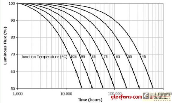
Figure 1. Relationship between light attenuation and junction temperature
Moreover, the junction temperature not only affects the long-term life, but also directly affects the short-term luminous efficiency. For example, the relationship between the luminous output and junction temperature of Cree's XLamp7090XR-E is shown in Figure 2.
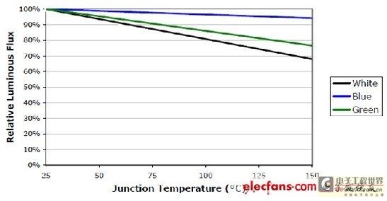
If the luminescence at a junction temperature of 25 degrees is 100%, then when the junction temperature rises to 60 degrees, the luminescence is only 90%; when the junction temperature is 100 degrees, it drops to 80%; and at 140 degrees, it is only 70%. It can be seen that improving heat dissipation and controlling junction temperature are very important.
In addition, the heat generated by LEDs will also cause their spectrum to shift, color temperature to rise, forward current to increase (when powered by constant voltage), reverse current to increase, thermal stress to increase, and aging of phosphor epoxy resin to accelerate, etc. Therefore, heat dissipation of LEDs is the most important issue in the design of LED lamps.
Part 1: Heat dissipation of LED chips
1. How is junction temperature generated?
The reason why LEDs generate heat is that the added electrical energy is not completely converted into light energy, but part of it is converted into heat energy. The luminous efficiency of LEDs is currently only 100lm/W, and its electro-optical conversion efficiency is only about 20-30%. In other words, about 70% of the electrical energy is converted into heat energy.
Specifically, the LED junction temperature is caused by two factors.
1. The internal quantum efficiency is not high, that is, when electrons and holes recombine, photons cannot be generated 100%, which is usually called "current leakage" and reduces the recombination rate of carriers in the PN region. The leakage current multiplied by the voltage is the power of this part, which is converted into heat energy, but this part does not account for the main component because the internal photon efficiency is now close to 90%.
2. The photons generated internally cannot all be emitted to the outside of the chip and are finally converted into heat. This part is the main one, because currently this so-called external quantum efficiency is only about 30%, and most of it is converted into heat.
Although the luminous efficiency of incandescent lamps is very low, only about 15lm/W, they convert almost all electrical energy into light energy and radiate it out. Because most of the radiation energy is infrared, the luminous efficiency is very low, but it eliminates the problem of heat dissipation.
2. Heat dissipation of LED chip to the base plate
The characteristic of LED chips is that they generate extremely high heat in a very small volume. However, the heat capacity of the LED itself is very small, so the heat must be conducted away as quickly as possible, otherwise a very high junction temperature will be generated. In order to conduct the heat out of the chip as much as possible, people have made many improvements to the LED chip structure.
In order to improve the heat dissipation of the LED chip itself, the most important improvement is to use a substrate material with better thermal conductivity. Early LEDs only used Si silicon as a substrate. Later, it was changed to sapphire as a substrate. However, the thermal conductivity of the sapphire substrate is not very good (about 25W/(mK) at 100°C). In order to improve the heat dissipation of the substrate, Cree uses a silicon carbide substrate, which has a thermal conductivity (490W/(mK)) that is nearly 20 times higher than that of sapphire. In addition, sapphire requires silver glue to solidify the crystal, and the thermal conductivity of silver glue is also poor. The only disadvantage of silicon carbide is that it is relatively expensive. Currently, only Cree produces LEDs with silicon carbide as a substrate.
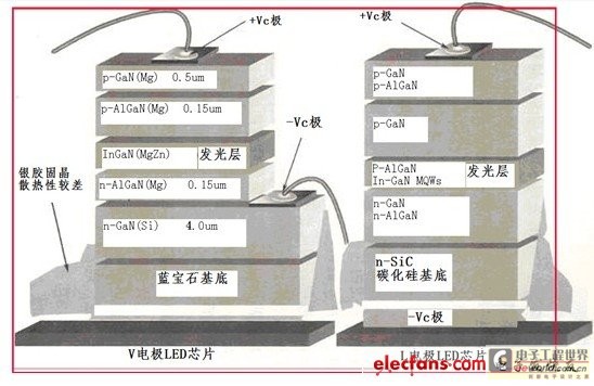
Figure 3. LED structure of sapphire and silicon carbide substrates
Using silicon carbide as the substrate can indeed greatly improve its heat dissipation, but its cost is too high and it is protected by patents. Recently, domestic manufacturers have begun to use silicon materials as the substrate. Because silicon material substrates are not restricted by patents. And the performance is better than sapphire. The only problem is that the expansion coefficient of GaN is too different from that of silicon, so it is easy to crack. The solution is to add a layer of aluminum nitride (AlN) in the middle as a buffer.
Substrate material Thermal conductivity W/(m·K) Expansion coefficient (x10E-6) Stability Thermal conductivity Cost ESD (antistatic)
Silicon Carbide (SiC) 490-1.4 Good High Good
Sapphire (Al2O3) 461.9 Generally 1/10 of SiC
Silicon (Si) 1505~20 Good, 1/10 of sapphire
After the LED chip is packaged, the thermal resistance from the chip to the pin is the most important thermal resistance in application. Generally speaking, the size of the chip's junction area is the key to heat dissipation. For different rated powers, a corresponding size of junction area is required. This is manifested as different thermal resistances. The thermal resistances of several types of LEDs are shown below:
Type Straw hat tube piranha 1W surface luminous
Thermal resistance ºK/W150-200508-155
Early LED chips were mainly led out of the chip by two metal electrodes. The most typical one is the straw hat tube called ф5 or F5. Its heat dissipation is completely led out by two thin metal wires, so the heat dissipation effect is very poor and the thermal resistance is very large. This is why the light decay of this straw hat tube is very serious. In addition, the material used in packaging is also a very important issue. Low-power LEDs usually use epoxy resin as a packaging material, but the absorption rate of epoxy resin for 400-459nm light is as high as 45%. It is easy to cause serious light decay due to aging caused by long-term absorption of this short-wavelength light. The life of 50% light decay is less than 10,000 hours. Therefore, silicone must be used as a packaging material in high-power LEDs. The absorption rate of silicone for the same wavelength of light is less than 1%. Thus, the life of the same light decay can be extended to 40,000 hours.
The following lists the thermal resistance of various types of LEDs produced by various LED chip companies.
Company Name Chip Model Chip Type Thermal Resistance °C/W
Everlight EHP53931W Cool White 13
Everlight EHP-A08L/UT011W, 5600K15
Edixeon S series1W,5K-8K13-14
Edixeon K series1W,8
LumenledLuxeon Emitter1W, 4.5K-5.5K15
NichiaNJSL036AT1W,30
CreeXLamp7090XR-E1W8
CreeXLampXP-G1W6
Lite-On LTW-M670ZVS(3020)0.07W, 20mA160
Lumins 30140.1W, 30mA45
As can be seen from the table, Cree's LED thermal resistance is at least twice as low as other companies' because it uses silicon carbide as the substrate. In order to improve heat dissipation, high-power LEDs usually put a solderable copper base plate under the base so that it can be soldered to the heat sink. These thermal resistances are actually measured on this copper base plate.
Is silicon carbide the best choice for LED substrate? No, everything will have innovation and development. Recently, Diamond Technology of Taiwan has developed Diamond Islands Wafer (DIW) as the substrate for producing super LED. The thermal resistance of this LED can be as low as <5°C/W. The super LED made of it can emit extremely strong ultraviolet light, and its intensity will not decrease due to high temperature, but will become brighter. Its structure is shown in Figure 4.
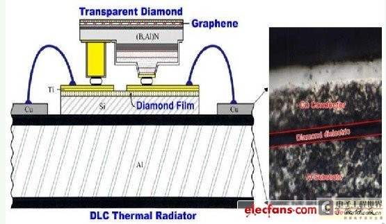
Figure 4. Diamond-like carbon (DLC) coating can greatly improve the heat dissipation of LEDs.
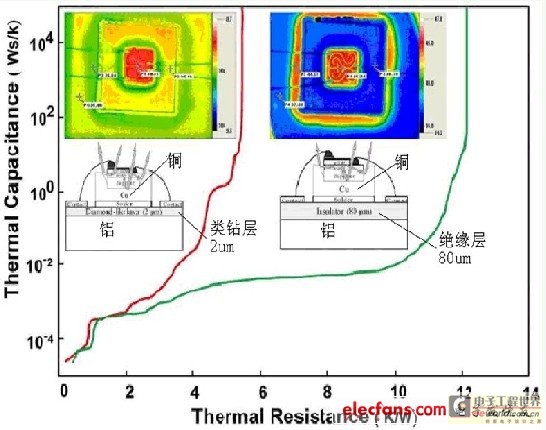
Figure 5. Combining DLC coating with aluminum can provide better heat dissipation characteristics than other LED structures.
Moreover, by using ultraviolet rays to excite various phosphors, LEDs of various colors can be obtained. Moreover, the phosphors are not mixed with epoxy resin or silicone but directly applied to the chip surface, which can also avoid the light decay caused by the aging of epoxy resin and silicone.
This will bring about a revolutionary change in the entire LED industry, and it will also get rid of the patent constraints of Japan, the United States and other countries.
3. Heat dissipation of integrated LED
Now many manufacturers integrate many LED chips together to obtain high-power LEDs. The power of this LED can reach more than 5W, and most of them appear in 10W, 25W, and 50W power levels. In order to connect multiple LED chips (in eutectic or flip-chip packages) together, because these chips are extremely fine, precise printed circuits are required for connection. In order to obtain better heat dissipation characteristics, ceramic substrates are usually used. This ceramic substrate is composed of aluminum oxide and aluminum nitride. The thermal conductivity of various materials is shown in the following table.
Material thermal conductivity W/mK
FR4 (glass fiber for ordinary printed circuit boards) 0.2
Alumina 17-27
Aluminum Nitride 170-230
Gold 315
Silver 425
Copper 398
Whether aluminum nitride or aluminum oxide, they are both insulating ceramic materials, so printed circuits can be made on them. However, aluminum nitride has a thermal conductivity 10 times higher, so aluminum nitride is more commonly used now. In the past, thick film circuits were used, but their surfaces were uneven, the edges of the circuits were rough, and sintering temperatures above 800°C were required. Now, thin film circuits are mostly used because they only require processes below 300 degrees, the surface flatness can be <0.3um, no oxide is generated, the adhesion is good, the circuit is fine, and the error is less than +/-1%. It is actually made using a photoetching method. The specific process of preparing a thin film circuit using aluminum oxide as a substrate is as follows:
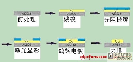
Figure 6. Thin film circuit fabrication process
The production method using aluminum nitride is the same.
Part 2: Heat dissipation of LED lamps
The previous part talked about the heat dissipation of LED chips. However, any LED will be made into a lamp, so the heat generated by the LED chip will always be dissipated into the air through the outer shell of the lamp. If the heat dissipation is not good, because the heat capacity of the LED chip is very small, a little bit of heat accumulation will cause the junction temperature of the chip to rise rapidly. If it works at a high junction temperature for a long time, its life will be shortened quickly. However, in order for this heat to be able to be truly guided out of the chip to the outside air, it must go through many channels. Specifically, the heat generated by the LED chip comes out of its metal heat sink, first passes through the solder to the PCB of the aluminum substrate, and then passes through the thermal conductive glue to the aluminum heat sink. Therefore, the heat dissipation of LED lamps actually includes two parts: thermal conduction and heat dissipation. Now let's take a look at the thermal conductivity of each link.
4. Thermal conductivity of various circuit substrates
Before connecting the LEDs to the heat sink, you must first solder them to the circuit, because you must first connect these LEDs into several series and parallels, and at the same time connect them to the constant current source in the circuit. The simplest way is to solder them directly to an ordinary printed circuit board. This is indeed possible for some very low-power LEDs, such as LED indicator lights. However, for most high-brightness and high-power LEDs, the thermal conductivity of ordinary fiberglass printed circuit boards is too poor, and they must be replaced with copper substrates, aluminum substrates, or even ceramic copper-clad substrates. The performance of various substrates is as follows:
Substrate Type Features
Ordinary printed circuit boards have mature technology and advantages in layout, but poor heat dissipation performance and large size, and are only suitable for low-power products.
Flexible printed circuits are light, bendable, thin, and have a thermal conductivity of approximately 2~3W/mK
High thermal conductivity aluminum substrate The printed circuit board base is aluminum plate, and the thermal conductivity is about 1~2.2W/mK
Ceramic copper clad laminate DCB has high thermal conductivity, about 200~800W/mK, which is difficult to manufacture and not easy to mass produce.
4.1 Aluminum substrate
At present, almost all LED lamps use aluminum substrates. The copper foil of the circuit on the aluminum substrate must have sufficient thickness and width for electrical and thermal conductivity, and its thickness is between 35µm-280µm. Its width is best to cover the entire substrate as much as possible to transfer heat. The lower layer of insulator requires good insulation performance and good thermal conductivity. However, these two properties are contradictory. Usually, the thermal conductivity of the conductor is good, while the thermal conductivity of the insulator is poor. It is difficult to achieve both good thermal conductivity and good insulation. It is also a scientific research topic. At present, a modified epoxy resin or epoxy glass cloth bonding sheet with ceramic filler is used. The copper foil insulator and the aluminum plate are bonded together by hot pressing. Some LED lamps, although the heat sink is carefully designed, will soon break down. The problem lies in the use of aluminum substrates with large thermal resistance or poor peeling strength. After a period of use, the circuit film will warp up, and it will be completely unable to conduct heat, and the LED will soon burn out.
For high-quality aluminum substrates, the thermal resistance is usually required to be less than 1°C/W. The following table shows the specifications of a certain aluminum substrate:
Performance Index Type I Aluminum PCB Type II Aluminum PCB
Thermal resistance (°C/W) Aluminum plate thickness 1.5mm<0.9<0.9
Peel strength(N/mm)1.82.0
Insulation resistance (MΩ) 107106
Breakdown voltage(KV)>3>3
Thermal shock (260°C) S (seconds) 120120
Flammability UL94V-0UL94V-0
Copper foil thickness (mm) 0.018, 0.035, 0.070
Dimensions (mm): 500x600x(0.5,1.0,1.5,2.0,2.5,3.0)
Foreign countries and Taiwan have been able to produce a "full-glue aluminum substrate". The so-called full glue means that its insulation layer does not use insulating cloth at all, but uses an insulating glue. The thermal resistance of aluminum substrates using insulating cloth is actually usually 1.7-3.2°C/W. The thermal resistance of aluminum substrates using full glue can be as low as 0.05°C/W, and the products sold on the market can be as low as 0.2-0.5°C/W.
A better performance aluminum substrate is to use ceramic printed circuits directly on the aluminum plate. First, a 100μm thick aluminum oxide film is grown on the surface of the aluminum by micro-arc oxidation, and then the circuit layer is made by sputtering or screen printing. The biggest advantage of this method is that it has strong bonding strength and a thermal conductivity of up to 2.1W/mK. In addition, the thermal expansion coefficient of the oxide layer is similar to that of aluminum, so its peel strength is as high as 5N/mm or more. However, this ceramic aluminum substrate is rarely used because of its complex processing and high cost.
Although the aluminum substrate is just a special printed circuit board, it has a heavy heat dissipation task. Not only does the insulation layer need to have good thermal conductivity and strong bonding, but its shape must also match the shape of the radiator. For example, in street lamps, it is usually a rectangular shape, in spotlights, it is usually round, and in fluorescent lamps, it is usually a long strip. In order to obtain better thermal conductivity, copper substrates with better thermal conductivity are sometimes used, but they are more expensive. And in the end, they still have to be connected to the aluminum radiator. There may be problems with cracking due to different thermal expansion coefficients.
4.2 Thermally conductive adhesive and thermally conductive double-sided tape
Although the aluminum substrate has solved the problem of connecting the LED to the circuit with the aluminum substrate, and can transfer heat to the aluminum plate, unfortunately, the aluminum plate is often not the final heat sink, and it is usually necessary to connect the aluminum plate to the real heat sink. The simplest method is to connect it to the heat sink by rivets or screws. However, this method often forms an air gap, and the thermal resistance generated by a very small air gap is dozens of times greater than other thermal resistances. Because the thermal conductivity of air is 0.023W/m•k. Therefore, thermal conductive glue must be applied to fill the gap. The thermal conductivity of general thermal conductive silicone is about 1-2W/m•k.
However, the thermal conductive adhesive must have good fluidity, otherwise air gaps will still be created due to uneven application, which may be worse than not using it. Another disadvantage of thermal conductive adhesive is that its own viscosity is not enough to fix the aluminum substrate on the aluminum heat sink.
Therefore, another method is to use a double-sided film with strong adhesion and thermal conductivity. This thermal conductive film is made of propylene series materials and is a heat conduction film with adhesiveness. It is a heat dissipation material with adhesiveness and low heat resistance. It also has thermal conductivity and softness, and can fit tightly to the concave and convex parts on the parts, thus preventing the existence of air gaps. The thermal conductivity of thermal conductive silicone sheets is usually between 2-3W/m•k. Its tensile strength can reach 8kg/cm2. It is enough to bond aluminum substrates and aluminum radiators. The withstand voltage can reach 4KV/mm.
4.3 Flexible Printed Circuit Board
From the structure of the aluminum substrate, people will definitely have such a question, why should the printed circuit be glued to a thin aluminum plate instead of directly glued to the heat sink? This can also save the process of drilling, applying thermal conductive glue, screwing, etc., and can also save the thermal resistance of thermal conductive glue. The main reason is that the shape of the heat sink is generally not a simple plane, and it is difficult to hot press bonding. In addition, the heat sink is designed and manufactured by the lighting factory, while the aluminum substrate is manufactured by the printed circuit board factory. The solution to this problem is to use a flexible printed circuit board and then stick it to the aluminum heat sink.
4.4LED is directly soldered to the aluminum heat sink. This is a more revolutionary and thorough solution. For high-power LEDs above 1W, its heat dissipation copper base plate is usually insulated from the two electrodes. In order to make it dissipate heat more directly, it is best to solder its heat dissipation base plate directly to the heat sink. However, general heat sinks are made of aluminum alloy and cannot be soldered. If a copper heat sink is used, this problem can certainly be solved, but both the price and weight are unacceptable. A simple solution is to spray copper on the aluminum heat sink. Then make a hole in the flexible printed circuit board so that the copper base plate of the LED is directly exposed to the heat sink surface, and then use low-temperature solder for soldering. This method can eliminate the thermal resistance of the aluminum substrate and the thermal resistance of thermal conductive silicone or silicon wafer. Thereby greatly improving the heat dissipation efficiency. In short, the fewer interfaces between the LED and the heat sink, the better.
5. Heat pipe heat conduction
In many cases, it is necessary to transfer the heat generated by the LED to the heat sink as quickly as possible. This is especially important when using integrated single-chip high-power LEDs, because their heat is very large (power can reach 50W-100W) and very concentrated (sometimes only 30mm). At this time, heat pipes must be used to dissipate heat.
Heat pipes are also called phase change heat conductors because the liquid in them changes from liquid phase to gas phase to conduct heat. Its thermal resistance is very small, only about 0.065°C/W.

Figure 7. Heat pipe heat conduction principle
The inner wall is sintered with copper powder to facilitate the heat carrier that has turned back into liquid phase to adsorb on it and reflux. However, the heat pipe can only transfer heat to the far end, but does not dissipate the heat into the air. Therefore, even if a heat pipe is used, an ordinary aluminum radiator is still required to dissipate the heat. Once again, it should be noted that after using the copper heat pipe, special attention should be paid to the joints between it and the aluminum substrate at the front end and the aluminum radiator at the rear end to ensure close contact with each other and prevent them from being separated due to different thermal expansion coefficients. High-quality thermal conductive silicone coating should be used at the joints.
The loop heat pipe has better thermal conductivity
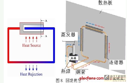
Figure 8. Loop heat pipe
The biggest advantage of the loop heat pipe is that it can circulate heat without an external power device, has a long heat conduction distance, has a large transmission power (several hundred watts), has a variety of shapes and is not restricted by gravity requirements, which means it can be placed anywhere. After Taiwan's Yangjie Technology Company adopted the loop heat pipe technology, the weight of a 150W LED street light is only 8.5 kg, and the weight of a 100W LED street light is only 5.5 kg.
The thermal conductivity of each part can also be described by the thermal resistance of the system. The structural diagram of an LED lamp is shown in Figure 9.
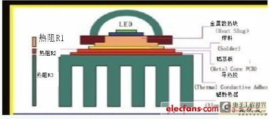
Figure 9. Heat dissipation structure of LED lamps
As can be seen from the figure, the heat generated by the LED chip comes out of its metal heat sink, first passes through the solder to the PCB of the aluminum substrate, and then passes through the thermal conductive adhesive to the aluminum heat sink. To quantitatively understand the heat dissipation process of the LED chip, it is best to use the concept of thermal resistance. Heat is like an electric charge, and the flow of heat is like electric current. During the flow, it will encounter resistance, just like resistance, which we call thermal resistance here. The unit of thermal resistance is how many degrees per watt (°C/W), that is, how many degrees the temperature will rise for every 1 watt of power flowing through. If you know the power to be dissipated and its thermal resistance, you can know its temperature rise. The greater the thermal resistance, the more difficult it is for the heat to flow, and the higher the temperature rise. The smaller the thermal resistance, the faster the heat flows, and the smaller the temperature rise. The figure shows that heat needs to pass through many different thermal resistances to flow from the LED chip to the air:
Rj1: Thermal resistance from chip to mounting base (also known as thermal resistance of chip)
Rj2: Thermal resistance of solder
Rj3: Thermal resistance of aluminum substrate
Rj4: Thermal resistance of thermally conductive silicone
Rj5: Thermal resistance from heat sink to air
So the total thermal resistance from chip to air should be:
Rja=Rj1+Rj2+Rj3+Rj4+Rj5
As long as the total thermal resistance from the chip to the air is known, the junction temperature can be calculated based on the power Pd that needs to be dissipated. Knowing the junction temperature also allows us to know its lifespan.
Assuming the ambient temperature is Ta, the junction temperature is:
Tj=Pd(Rj1+Rj2+Rj3+Rj4+Rj5)+Ta
However, in actual LED lamps, the thermal resistance from the LED chip to the air is much greater than this. For example, thin-film printed circuit boards are usually mounted on aluminum substrates, which are then mounted on aluminum heat sinks, and thermal conductive adhesive is applied in between. The thickness of the thermal conductive adhesive is difficult to estimate, and there are residual air gaps. For lamps using heat pipes, the gap between the heat pipe and the heat sink fins and the thermal resistance of the thermal conductive adhesive must also be considered.
And the most difficult to estimate is Rj5, which is the thermal resistance from the heat sink to the air. This involves many issues related to the heat dissipation mechanism of convection and radiation.
It should be noted that when calculating the heat dissipation of LEDs, a common mistake is to take the full power of the LED as its dissipated power Pd. For example, a 1W LED has a forward voltage of 3.3V and a forward current of 350mA. So the product of the two, 1.155 watts, is taken as its dissipated power. This is wrong. Because this is only its input power, not its dissipated power. A part of the input power is emitted as useful light. The part that needs to be dissipated as heat should be the input power minus the part emitted in the form of useful light, which is the part that needs to be dissipated as heat. However, this part is more difficult to calculate. Generally speaking, because the luminous efficiency of LEDs is different, the dissipated power is also different. Generally speaking, the following approximation can be made: the luminous efficiency is 100lm/W, and its dissipated power should be 70% of the input power. For the 1W LED mentioned above, that is, 1.155x0.7=0.8W becomes useless heat that needs to be dissipated.
So if we know the thermal resistance of all parts, can we know the total thermal resistance of the LED lamp, the junction temperature of the LED chip, and the life of the lamp?
The situation is far from simple. Although we can carefully analyze the thermal resistance of each part and even get a relatively accurate number, there are still many important factors that we have overlooked. This is because the above model is only a model of a single LED lamp, and the actual lamp is much more complicated than this model.
1. Distribution of LEDs. In many cases, LED lamps are made up of many LEDs instead of just one LED. Maybe all these LEDs are soldered on an aluminum substrate. At this time, if you only use the standard thermal resistance of the aluminum substrate to calculate the thermal resistance of the entire lamp, there will be a big discrepancy. This is because the heat dissipation of each LED will be affected by the heat emitted by the surrounding LEDs. In other words, the thermal resistance of the aluminum substrate is difficult to calculate.
2. The influence of other heat sources, such as the constant current power supply of LED is an important heat source. If this heat source is close to some LEDs, it will significantly reduce the heat dissipation of these LEDs and shorten their lifespan, which is equivalent to changing their thermal resistance.
3. Thermal resistance actually only considers heat conduction, and does not consider heat convection and heat radiation at all. Heat starts from the LED chip, passes through a series of different materials, and finally reaches the fin heat sink. All this heat will eventually dissipate into the air. If it cannot be dissipated into the air, then the heat will accumulate more and more, leading to an increase in the junction temperature. So it can be said that the final link of the fin heat sink dissipating into the air is the most critical link, the most complex link, and the most difficult to calculate. In other words, Rj5 basically cannot be calculated by simple calculation. This makes it almost impossible to calculate the junction temperature of the LED through the thermal resistance of all components.
7. Radiator design
When talking about heat sinks, there is a concept that needs to be clarified first, which is the difference between heat conduction and heat dissipation. Heat conduction is to transfer heat from the heat source to the surface of the heat sink as quickly as possible, while heat dissipation is to dissipate heat from the surface of the heat sink to the air. First, the heat must be conducted out as quickly as possible, and then it must be dissipated into the air most effectively. Because no matter what method is used to dissipate heat, in the end, the heat can only be dissipated into the air. And there are only two ways to dissipate heat: convection and radiation.
7.1 Convection and radiation cooling
For convection cooling, the basic formula is as follows:
Q=h•A•△T
Where Q is the heat dissipated, h is the heat convection coefficient, A is the heat dissipation area of the radiator, and △T is the temperature difference between the radiator surface and the nearby air.
To be more vivid, it can be represented by Figure 10:
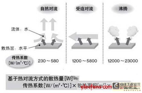
Figure 10. Calculation of heat dissipation based on convection
The heat dissipation of fins mainly relies on convection and radiation, among which convection is the most important. Both parts depend on the total area of the fins. The larger the area, the better the heat dissipation effect. However, convection heat dissipation does not entirely depend on the size of the fin area, but is also related to the wind force and direction. In a completely windless state, it is related to the resistance of natural convection. For example, if the fins are installed downwards to prevent dust and bird droppings from accumulating, the two ends of the fins cannot be blocked, and the lamps are either tilted downwards or upwards to allow the hot air to flow smoothly.
The heat dissipation formula of thermal radiation is "Q=E×S×F×Δ(Ta-Tb)". In the formula, Q represents the ability to exchange heat radiation, and E is the thermal radiation coefficient of the surface of the object. In practice, when the material is metal and the surface is smooth, the thermal radiation coefficient is relatively small, and after the metal surface is treated (such as blackening), the value of its surface thermal radiation coefficient will increase. Most of the thermal radiation coefficient values of plastics or non-metals are relatively high. S is the surface area of the object, and F is the functional relationship between the angle of radiation heat exchange and the surface, but this function is more difficult to explain here. Δ(Ta-Tb) is the temperature difference between surface a and surface b. Therefore, there is a proportional relationship between the amount of thermal radiation and the thermal radiation coefficient, the size of the surface area of the object, and the temperature difference. The radiation coefficient of an absolute black body is 1. Heat dissipation by thermal radiation can also be expressed by another formula:
As can be seen from the table, oxidation treatment is an important way to improve the radiation heat dissipation of materials. A considerable part of the heat dissipation of cast iron radiators depends on radiation heat dissipation. Moreover, the thermal radiation performance of plastics is similar to that of oxidized metals.
In order to improve radiation heat dissipation, the aluminum alloy fin heat sink needs to be blackened, but some people use the method of spraying black plastic paint. Although this method also makes the surface black, it actually adds an insulating layer, which hinders its heat dissipation. The best method is to use anodizing blackening treatment. This oxide layer can be made very thin and will not affect its heat dissipation, but it will greatly improve radiation heat dissipation.
In short, both convection and radiation are proportional to the heat dissipation area of the radiator, so to improve heat dissipation, the area of the radiator must be increased.
8. Fin radiator
The fin shape of the heat sink is to increase the heat dissipation area. This is conducive to radiation heat dissipation and convection heat dissipation. The most important indicator of a heat sink is its heat dissipation area A, but the heat dissipation effect of different parts of the heat sink is different. The heat dissipation effect at the root is poor, while the heat dissipation effect at the top is good. Therefore, the heat sink has an effective heat dissipation area. It is usually about 70% of the actual area. From experience, it is generally necessary to dissipate 1W of heat with an effective heat sink area of about 50-60 square centimeters.
The material of the radiator is usually aluminum alloy. Compared with copper, although its thermal conductivity is only half of that of copper, it is light, easy to process, and cheap, so it is still widely used in radiators. A typical heat dissipation aluminum alloy profile is shown in Figure 11.
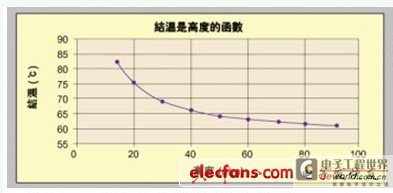
Figure 11. Typical finned aluminum alloy heat sink
In order to increase the heat dissipation area, the method of increasing the height is usually adopted. However, after the height increases to a certain extent, its effect will become smaller and smaller. Figure 12 shows an example of the effect of increasing the height on reducing the junction temperature.
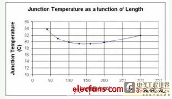
Figure 12. LED junction temperature decreases as heat sink height increases
It can be seen from the figure that after the height increases to 40mm, the junction temperature decreases very slowly.
Increasing the length is also a way to increase the area, but it does not mean that the longer the better.
As can be seen from the figure, when the length increases to a certain extent, the junction temperature will not only stop decreasing, but will increase. This is because the air flow along the length direction is hindered (mainly for vertically placed fins).
Therefore, for the radiator, in addition to increasing the area, how to accelerate the convection of air is very important, especially for street lights such as LED street lights installed outdoors. Since the wind direction outdoors is uncertain, in order to have good convection under various wind directions, it is best to use a pin-shaped fin radiator. However, this also reduces its equivalent heat dissipation area by a large percentage.
Zhuhai Nanke applied needle-shaped heat sinks to LED street lights for the first time. It is said that this can reduce the junction temperature of the LED by more than 15 degrees and increase the life of the LED.
Street lamp radiators often have a greatly reduced heat dissipation effect due to the accumulation of dust and bird droppings, so they are usually installed downwards to avoid this, but this will reduce the effect of air convection because hot air flows upwards. Usually, an inclined angle is required during installation to improve this.
9. Use forced air cooling
At present, almost all LED lamps use natural air convection to dissipate heat. However, the heat dissipation effect of convection is closely related to the air flow rate. In a 15W LED lamp, if forced air cooling is used, the relationship between the LED junction temperature and the wind speed can be obtained as shown in Figure 15.
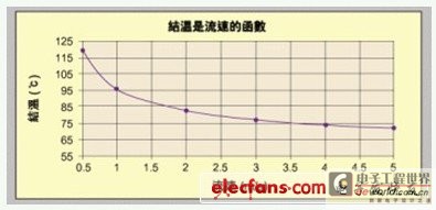
Figure 15. Relationship between LED junction temperature and wind speed
In computer CPUs, forced air cooling systems with small fans have always been used to dissipate heat. So can fans also be used to dissipate heat in LEDs?
The LED street lamp is the most powerful LED lamp currently. The biggest difference between LED street lamp and computer is that it is installed outdoors in very harsh environmental conditions. If a fan is used, then this fan must also be able to withstand very harsh environmental conditions. For example, it must be waterproof, moisture-proof, dust-proof, able to withstand high and low temperature tests, etc. And it itself cannot consume a lot of power.
Recently, Taiwan Sunon Company launched the world's smallest, thinnest and lowest power consumption "MightyMiniFan&Blower". It is used in LED lamps of various powers. For example, when applied to LED bulbs, it can break through the bottleneck limit of 9W and reach the level of 15W. At the same time, the LED heat dissipation module designed with the new "One-module" concept was displayed, which modularizes the heat dissipation of LED lamps. One heat dissipation module can be applied to multiple LED lamps, simplifying the design process of the client. It is expected to launch several power levels of 7-15W, 10-25W, and 25-40W. It can be used for heat dissipation of various LED application products such as LED ball lamps, downlights, MR16 projection lamps, and LED track lights.
10. Conclusion
At present, the luminous efficiency of LED is still relatively low, which causes the junction temperature to rise and the life span to decrease. In order to reduce the junction temperature and increase the life span, it is necessary to pay great attention to the problem of heat dissipation. The heat dissipation design of LED must start from the chip to the entire heat sink, and every link must be given full attention. Improper design of any link will cause serious heat dissipation problems. In the past, a large number of LED street lamps failed in long-term work, more than half of which were caused by insufficient heat dissipation design, and the other half were caused by power failure. Therefore, full attention must be paid to the heat dissipation design. As the light efficiency of LED increases year by year, its heating problem will gradually decrease. I believe that one day we will see the emergence of LED lamps that do not require heat sinks!
Previous article:Daily LED cool design: DIY waterproof flashlight
Next article:Special use of 5×7 LED dot matrix screen
Recommended ReadingLatest update time:2024-11-16 21:52


- Popular Resources
- Popular amplifiers
- MathWorks and NXP Collaborate to Launch Model-Based Design Toolbox for Battery Management Systems
- STMicroelectronics' advanced galvanically isolated gate driver STGAP3S provides flexible protection for IGBTs and SiC MOSFETs
- New diaphragm-free solid-state lithium battery technology is launched: the distance between the positive and negative electrodes is less than 0.000001 meters
- [“Source” Observe the Autumn Series] Application and testing of the next generation of semiconductor gallium oxide device photodetectors
- 采用自主设计封装,绝缘电阻显著提高!ROHM开发出更高电压xEV系统的SiC肖特基势垒二极管
- Will GaN replace SiC? PI's disruptive 1700V InnoMux2 is here to demonstrate
- From Isolation to the Third and a Half Generation: Understanding Naxinwei's Gate Driver IC in One Article
- The appeal of 48 V technology: importance, benefits and key factors in system-level applications
- Important breakthrough in recycling of used lithium-ion batteries
- Innolux's intelligent steer-by-wire solution makes cars smarter and safer
- 8051 MCU - Parity Check
- How to efficiently balance the sensitivity of tactile sensing interfaces
- What should I do if the servo motor shakes? What causes the servo motor to shake quickly?
- 【Brushless Motor】Analysis of three-phase BLDC motor and sharing of two popular development boards
- Midea Industrial Technology's subsidiaries Clou Electronics and Hekang New Energy jointly appeared at the Munich Battery Energy Storage Exhibition and Solar Energy Exhibition
- Guoxin Sichen | Application of ferroelectric memory PB85RS2MC in power battery management, with a capacity of 2M
- Analysis of common faults of frequency converter
- In a head-on competition with Qualcomm, what kind of cockpit products has Intel come up with?
- Dalian Rongke's all-vanadium liquid flow battery energy storage equipment industrialization project has entered the sprint stage before production
- Allegro MicroSystems Introduces Advanced Magnetic and Inductive Position Sensing Solutions at Electronica 2024
- Car key in the left hand, liveness detection radar in the right hand, UWB is imperative for cars!
- After a decade of rapid development, domestic CIS has entered the market
- Aegis Dagger Battery + Thor EM-i Super Hybrid, Geely New Energy has thrown out two "king bombs"
- A brief discussion on functional safety - fault, error, and failure
- In the smart car 2.0 cycle, these core industry chains are facing major opportunities!
- The United States and Japan are developing new batteries. CATL faces challenges? How should China's new energy battery industry respond?
- Murata launches high-precision 6-axis inertial sensor for automobiles
- Ford patents pre-charge alarm to help save costs and respond to emergencies
- New real-time microcontroller system from Texas Instruments enables smarter processing in automotive and industrial applications
- MSP430F5438A
- Could you recommend a replacement chip for PGA280?
- 180,000 for 5 kicks? What kind of screen is this? It's so expensive! Is there gold in the screen?
- Evaluation summary: Xingkong Board Python programming learning control board
- National epidemic statistics in the past 11 days, please pay attention if you are visiting relatives
- Problems encountered during ads2020 installation
- MSP430 MCU Simulation Example 19-D/A Conversion Sine Wave Generator Based on Proteus
- Serial communication based on stm32 code implementation
- RF power testing is that simple when explained thoroughly!
- Some concepts in FPGA

 Siemens PLC Project Tutorial
 LED Cube Code
 ESP32-S3 source code


 京公网安备 11010802033920号