1 Introduction
In recent years, semiconductor light sources are gradually entering the lighting field as a new type of solid light source. According to the principles of solid-state light emitting physics, the luminous efficiency of LED can be close to 100%. It has the advantages of low operating voltage, low power consumption, short response time, high luminous efficiency, impact resistance, long service life, pure light color, stable and reliable performance and low cost. With the continuous reduction of LED prices and the continuous improvement of luminous brightness, semiconductor light sources have shown a wide range of application prospects in the field of lighting. The volt-ampere characteristics of LED are the same as those of ordinary diodes. A small fluctuation in forward voltage will cause a sharp change in forward current. The magnitude of LED forward current will change with the ambient temperature. When the environment reaches a certain temperature, the allowable forward current of LED will drop sharply. In this case, if a large current is still passed, it is easy to cause LED aging and shorten the service life. Therefore, LED needs an LED drive system with constant temperature and constant current control and reliable protection function during application. This article introduces a design method for an intelligent LED drive system.
2 LED Model
LED is a PN junction optoelectronic semiconductor device driven by low voltage. The relationship between its voltage and current can be expressed by equation (1).
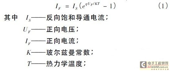
q———electron charge.
After the LED forward voltage exceeds the threshold voltage, the LED forward current increases rapidly with the increase of the forward voltage. A small voltage fluctuation will cause a large change in current.
The volt-ampere characteristic of LED has nonlinear and unidirectional conductivity. When the forward voltage is less than a certain value, the current is extremely small and no light is emitted. When the forward voltage exceeds a certain value, the forward current increases rapidly as the forward voltage increases. The volt-ampere characteristic model of LED can be expressed by formula (2).

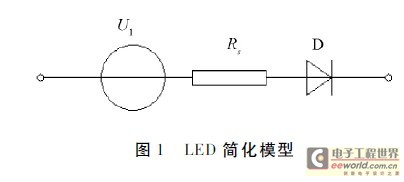
The simplified LED model reflects the volt-ampere characteristics of the LED and is used to analyze the impact of the circuit driving current on the electrical characteristics of the LED to verify the correctness of the analysis and design.
3 System Design
The performance of the LED drive system directly affects the working life and working stability of the light source system. This drive system is mainly composed of three parts: switching power supply, constant current drive circuit, and single-chip constant current control. The system principle block diagram is shown in Figure 2.
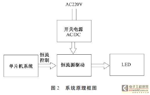
This system adopts a method that combines hardware circuit design and software program design, with single-chip control as the core. It adjusts the output current through negative feedback to achieve adjustable brightness. It is an intelligent drive control system suitable for a variety of LED lamps, which improves and enhances the performance of LEDs and solves the problems of LED light source output stability and reliability.
3.1 Switching Power Supply
LED lighting can only be powered by DC. Under AC220V power supply, the AC/DC conversion problem must be solved first. Switching power supplies have the advantages of high conversion efficiency, small size and light weight, wide input range, flexible use and energy saving. Switching power supplies generally use semiconductor power devices as switches to convert one power form into another, automatically control stable output during conversion, and have multiple protection circuits.
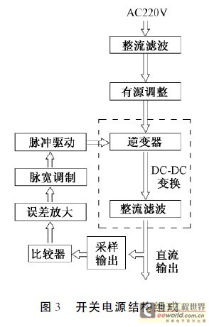
The structure of the switching power supply is shown in Figure 3. After low-pass filtering and bridge rectification, the 220V AC power is converted into an unregulated DC voltage. This DC voltage undergoes active power factor correction to improve the power factor of the power supply. The DC voltage then passes through the inverter to become a high-frequency square wave pulse voltage that meets the requirements. After rectification and filtering, it becomes a DC voltage output. After voltage division and sampling, the output voltage is compared with the reference voltage through a comparison circuit, the error is amplified, and the pulse width is adjusted through pulse width modulation. Pulse width modulation (PWM) is the most commonly used method in switching power converters.
3.2 Constant current drive circuit
Under certain voltage and temperature changes, the constant current source produces a current change close to zero, with a constant current value and a very high dynamic output resistance. Generally, the constant current drive circuit is composed of electron tubes, transistors, constant current devices, integrated circuits, integrated voltage regulators and other components. In order to be suitable for the application of LED lamps, the constant current source must not only have high stability and current output accuracy, but also the output current of the constant current drive circuit is designed to be adjustable. In order to ensure the accuracy of the output current, this design uses a single-chip microcomputer system D/A to convert the output voltage and adjust the output current of the constant current source. The schematic diagram is shown in Figure 4.
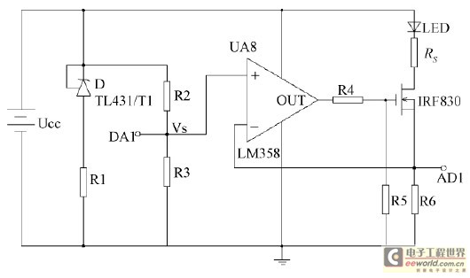
This constant current drive circuit belongs to the topology of current series negative feedback, in which LED is the load and R6 is the sampling resistor. In this design, in order to realize the control of adjustable constant current source, the adjustable voltage signal Vs output by the single-chip system D/A is introduced at the in-phase input of the operational amplifier to make it a controlled constant current source, that is, the reference voltage. The sampling resistor R6 is connected to the reverse input. The operational amplifier works in a deep negative feedback state. It cooperates with the power MOS tube to follow the input reference voltage Vs through feedback. The power MOS tube is connected to the base of the operational amplifier to increase the driving current. When the input voltage of the in-phase end of the operational amplifier is constant, the output voltage is guaranteed to be constant due to the existence of negative feedback, so that the current flowing through the LED load is a constant current. The output current of the constant current source directly depends on the ratio of the output voltage of the D/A and the sampling resistor R6. Since the operational amplifier is used in the feedback link, the loop gain of the feedback loop is increased, the feedback depth is increased, and the output impedance of the constant current drive circuit is large, which meets the use requirements.
The output current is directly related to the input control voltage VS. The offset of the op amp has the same effect on the output current as VS. Therefore, the stability of the output current depends on the stability of the controlled voltage VS and the offset drift of the op amp. Selecting a high-stability reference voltage source as the control voltage and a low-drift operational amplifier is an important way to improve the output current stability of this circuit. The integrated operational amplifier LM358 used in the circuit includes two independent, high-gain, internal frequency-compensated operational amplifiers, which have the advantages of high gain and small offset voltage influence.
3.3 Single chip microcomputer constant current control
In order to obtain a stable driving current and improve the light stability of the LED, this system changes the peripheral voltage of the constant current source and uses the change in voltage to control the output current. The control part of this system is based on the single-chip microcomputer system, combined with button input and LED digital display. The A/D sampling voltage is compared with the input voltage through closed-loop feedback, and corresponding adjustments are made. Finally, the analog voltage output by the D/A conversion is used as the reference input voltage of the constant current source.
3.3.1 MCU Hardware System
The single-chip microcomputer system mainly consists of AT89C51, ADC0809, DAC0800, digital tube, buttons and other parts. The schematic diagram of the single-chip microcomputer system is shown in Figure 5.
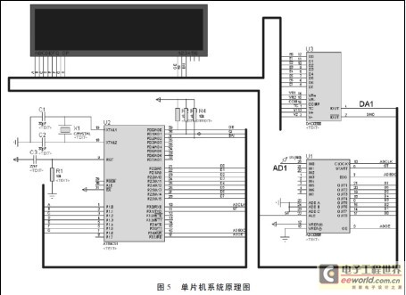
The sampled analog voltage is input to the input of ADC0809, and after conversion by ADC0809, an 8-bit binary number is output to the microcontroller port. The microcontroller converts the obtained 8-bit binary number into a 3-bit decimal number and displays it on the digital tube. At the same time, the current value is compared with the reference value, and the software system makes corresponding adjustments and controls. The microcontroller system software calculates and outputs an 8-bit binary value, which is converted to D/A by DAC0800 and output to the DA1 port. The voltage of the DA1 port is input to the constant current drive circuit, and the reference voltage VS is adjusted to realize the constant current drive circuit output current design as an adjustable output.
3.3.2 MCU Software System
In the system design, the software program design mainly includes the initialization management module, the button management module, the data processing module and the display module. All modules are written in the microcontroller assembly language.
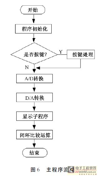
After the system is powered on, the main program must first complete the system initialization, including the setting of the working status of A/D, D/A, display, etc., assigning initial values to system variables, displaying the last set values, etc. Then scan and obtain the key values, determine whether the setting key and calibration key are pressed, and execute the corresponding function subroutine. When the start key is pressed, D/A and A/D conversion are performed according to the set value, and the sampled value and the set value are compared and corrected through the control algorithm and other parameter calculations, and finally closed-loop feedback adjustment is performed to obtain an accurate constant current value. The main program flow of the microcontroller software is shown in Figure 6.
4 System Testing
The system has been tested for load changes. When LEDs with different powers are working, the changes in system voltage and current are detected.
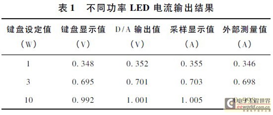
Test system performance. The measuring instruments used in this system test are: oscilloscope, digital multimeter. The load change test uses 1W, 3W, and 10W LEDs commonly used in the market, and adds 9V, 12V, and 15V power supply voltages in turn. The output current value corresponding to the selected power LED is set by the button (1W-0.35mA; 3W-0.75mA; 10W-1A). The corresponding D/A conversion output voltage, the actual output current value detected by the current source itself, the current value measured by the external ammeter, and the two data display values of the digital tube are detected respectively. The values of the performance parameters of different power LEDs in the actual output measurement are shown in Table 1.
5 Conclusion
The system design is based on constant current source drive, which completes the real-time monitoring and high-precision adjustable control of the driving current of LED lighting fixtures, and realizes the LED brightness adjustment control, meeting the current requirements of various LED lighting fixtures for stable light emission. Practice has proved that the design method of LED lighting drive system introduced in this article is safe, reliable and highly stable.
Previous article:Characteristics and development of solar LED lighting system
Next article:Simulation design of free-form lens for achieving uniform illumination of LED desk lamp
- MathWorks and NXP Collaborate to Launch Model-Based Design Toolbox for Battery Management Systems
- STMicroelectronics' advanced galvanically isolated gate driver STGAP3S provides flexible protection for IGBTs and SiC MOSFETs
- New diaphragm-free solid-state lithium battery technology is launched: the distance between the positive and negative electrodes is less than 0.000001 meters
- [“Source” Observe the Autumn Series] Application and testing of the next generation of semiconductor gallium oxide device photodetectors
- 采用自主设计封装,绝缘电阻显著提高!ROHM开发出更高电压xEV系统的SiC肖特基势垒二极管
- Will GaN replace SiC? PI's disruptive 1700V InnoMux2 is here to demonstrate
- From Isolation to the Third and a Half Generation: Understanding Naxinwei's Gate Driver IC in One Article
- The appeal of 48 V technology: importance, benefits and key factors in system-level applications
- Important breakthrough in recycling of used lithium-ion batteries
- Innolux's intelligent steer-by-wire solution makes cars smarter and safer
- 8051 MCU - Parity Check
- How to efficiently balance the sensitivity of tactile sensing interfaces
- What should I do if the servo motor shakes? What causes the servo motor to shake quickly?
- 【Brushless Motor】Analysis of three-phase BLDC motor and sharing of two popular development boards
- Midea Industrial Technology's subsidiaries Clou Electronics and Hekang New Energy jointly appeared at the Munich Battery Energy Storage Exhibition and Solar Energy Exhibition
- Guoxin Sichen | Application of ferroelectric memory PB85RS2MC in power battery management, with a capacity of 2M
- Analysis of common faults of frequency converter
- In a head-on competition with Qualcomm, what kind of cockpit products has Intel come up with?
- Dalian Rongke's all-vanadium liquid flow battery energy storage equipment industrialization project has entered the sprint stage before production
- Allegro MicroSystems Introduces Advanced Magnetic and Inductive Position Sensing Solutions at Electronica 2024
- Car key in the left hand, liveness detection radar in the right hand, UWB is imperative for cars!
- After a decade of rapid development, domestic CIS has entered the market
- Aegis Dagger Battery + Thor EM-i Super Hybrid, Geely New Energy has thrown out two "king bombs"
- A brief discussion on functional safety - fault, error, and failure
- In the smart car 2.0 cycle, these core industry chains are facing major opportunities!
- The United States and Japan are developing new batteries. CATL faces challenges? How should China's new energy battery industry respond?
- Murata launches high-precision 6-axis inertial sensor for automobiles
- Ford patents pre-charge alarm to help save costs and respond to emergencies
- New real-time microcontroller system from Texas Instruments enables smarter processing in automotive and industrial applications
- Which environment setup tutorial should I watch? -- ESP series development environment setup video navigation directory
- CC2640R2F-Q1 uses low-power Bluetooth technology to transform car access control systems
- Problems with opening KEIL in WIN10
- MSP430 MCU Development Record (25)
- BK3432 BK3432 BLE Bluetooth Chip DataSheet & Hardware Layout Guide
- Test the SCI (UART) communication of 28379D
- msp430fr2311 MCU ADC serial channel sampling
- [Flower carving hands-on] Interesting and fun music visualization series projects (30)--P6 LED unit board
- (There are three lights in the room, how to distinguish them) How to solve this interview question? ?
- EEWORLD University Hall----Live Replay: Littelfuse Silicon Carbide (SiC) MOSFET and Schottky Diode Product Introduction and Related Applications

 Characteristic Modes——Theory and Applications in Antenna Engineering


 京公网安备 11010802033920号