1 Introduction
With the improvement of people’s quality of life, lamps are no longer just basic indoor lighting tools, but also a practical art for architectural decoration. When there are various lamps in the home, they must be carefully matched together. Achieving the most suitable atmosphere effect is a need for high-quality life. At present, lighting control is mainly manual, and all lamps are controlled one by one. This is not only troublesome but also inefficient, and does not meet the standards of modern comfortable life.
Therefore, designing an intelligent lighting system that can easily control lights and also provide scene combination and other functions not only has practical value, but also has broad market prospects.
2 Design Goal
: Design an intelligent lighting controller that can be installed in every room of the home to provide rich functions such as wireless remote control, light-touch lighting control, scene combination, and preset storage. Use the handheld remote control to control all the lights in the house; use the scene setting button on the remote control to easily set the lighting scene and quickly switch. You can control the switch and brightness of the light, or multiple lights, through the touch button on the panel. The lights enter a certain preset scene, and each lighting controller communicates with the home Ethernet network terminal through the RS485 bus to realize remote control and query of the light brightness.
The intelligent lighting control system is divided into two parts: receiving external control signals and executing control operations. In order to receive control signals, the system needs to have a wireless receiving function and a key input panel. In order to control the lamps, a 220V dimming control circuit needs to be designed.
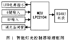
LPC2104 has rich peripheral interface resources, high reliability and computing speed, and is very suitable for the design of this system. The principle of the intelligent lighting controller is shown in Figure 1.
 |
3 LPC2104 Function Introduction
LPC2104 is a cost-effective microcontroller solution specially provided by PHILIPS for embedded applications. It adopts ARM's 16-bit/32-bit RISC structure. The core is ARM7TDMI-S. The CPU operating frequency can reach 60MHz. On-chip integration: 128KB Flash program memory with ISP and IAP functions, 16KB static RAM, 2 UARTs, 1 I2C serial interface, 1 SPI serial interface, up to 6 output PWM, 2 timers, each with 4 capture/compare channels, real-time clock and watchdog timer, etc., can be connected with commonly used peripheral devices To achieve seamless connection and powerful functions, this article uses LPC2104 as the core to design an intelligent lighting controller with simple structure and stable performance.
4 Wireless data transmission module design
4.1 Introduction to nRF401
There are three options for realizing wireless communication: Bluetooth communication, infrared wireless remote control, and the use of short-range wireless data transmission devices. For Bluetooth solutions, transmission distance and device cost are issues worth considering. Bluetooth is mainly used for short-distance transmission (up to 10m), and the cost has always been on the high side. Although infrared transmission does not need to consider the cost issue, from the perspective of the power consumption that handheld devices can provide, the distance it can transmit is too short, only a few meters, and there are certain requirements for the infrared emission angle. There are two "must ensure the transmission of information" "The devices are facing each other, and there can be no obstacles in the middle" and other fatal flaws. Compared with the first two solutions, the use of short-range and low-power wireless radio frequency device nRF401 is the best choice.
The nRF401 wireless communication transceiver integrates functions such as high-frequency transmission/reception, PLL synthesis, FSK modulation/demodulation and multi-channel switching. It has outstanding technical advantages in low-cost digital communication applications. Its main technical features are: (1) Works on two internationally common channels: 433.92MHz and 434.32MHz, which can be used without channel application; (2) Using DSS+PLL frequency synthesis technology, the external components are only a crystal oscillator and several resistors, capacitors and inductors , it can work basically without debugging and has good stability; (3) Digital communication adopts the FSK modulation method with high anti-interference ability, supports direct data input and output operations, and can be directly connected to the UART serial port of the MPU; ( 4) There are 2 selectable working channels, using half-duplex working mode, the maximum data transmission rate can reach 20bk/s; (5) The working voltage is 2.7V-5V, and the power consumption in standby state is only 8μA, which can meet the requirements of low Requirements for power consuming devices.
The nRF401 device does not require initialization and configuration, does not require Manchester encoding of data, and can use cheap PCB antennas without complex RF circuit design and debugging, making product development and application more convenient.
4.2 Connection between nRF401 and LPC2104
There are many options for connecting nRF401 and LPC2104, such as GPIO, I2C, UART, etc. From the perspective of the simplest hardware connection and communication protocol, it is the best solution to choose the serial port to connect to the wireless module. TXD1 and RXD1 of UART1 are respectively connected to DIN and DOUT connections of nRF401. The interface circuit between nRF401 and LPC2104 is shown in Figure 2.
 |
As can be seen from Figure 2, the control interface of the embedded CPU to the wireless module mainly consists of 5 signal lines, namely DIN, DOUT, TXEN, PWR_UP, and CS. Among them, TXEN is the transmission enable terminal. By setting and resetting TXEN, the transmission state and the reception state are switched and controlled through the GPIO port. PWR_UP is the energy-saving control terminal. It is programmed using a GPIO port of LPC2104 to achieve Switching between the working mode and sleep state of the wireless module; CS can select channels, and through GPIO settings, the UART1 serial port of LPC2104 can be used to control DIN and DOUT signals.
In order to save energy, nRF401 should be turned off in most cases. The wireless hardware does not have an automatic wake-up function. A reasonable communication protocol must be adopted through software to ensure energy saving without data loss.
5 The dimming control circuit design
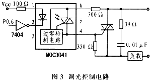
uses the method of sinking current through the I/O port of the microcontroller to control the thyristor to achieve switching and dimming control. The photoelectric coupler MOC3041 with an internal zero-crossing detection circuit is used as the thyristor driver, which can simultaneously realize the isolation of strong and weak currents.
Traditional dimming methods use phase-shifted trigger thyristors to control the output power by controlling the conduction angle of the thyristor. Not only is the synchronous detection circuit complex, but also high-order harmonic interference will be generated at the moment the thyristor is turned on, causing grid voltage waveform distortion and affecting The normal operation of other electrical equipment and communication systems. In this system, the time ratio between the on and off time of the zero-crossing trigger thyristor is used to adjust the power of the lamp. Since the zero-crossing trigger does not change the voltage waveform, it only changes the full wave of the voltage passing through. times and will not cause pollution to the power grid. Therefore, this system adopts the zero-crossing trigger method.
MOC3041 contains an internal zero-crossing detection circuit. When input pin 1 inputs a 15mA current and the voltage between output pins 6 and 4 slightly crosses zero, the internal bidirectional thyristor is turned on, triggering the external thyristor to turn on. When MOC3041 When the input current of the input pin is 0, the internal bidirectional thyristor is turned off, and the external thyristor is also turned off. The dimming control circuit is shown in Figure 3.
 |
6 Wireless module software design
The wireless module is connected to the system through the UART serial port, so the UART must be initialized. The UART serial port of LPC2104 complies with the RS232 standard and also supports the 550 industrial standard.
LPC2104 has two general-purpose asynchronous serial interfaces (UART). The UART default state is unavailable at startup, and they must be enabled by programming the GPIO register.
This system uses UART1 to connect with nRF401. UART1 has a modem interface and 16-byte receive and transmit FIFO. Built-in baud rate generator and contains standard modem interface signals.
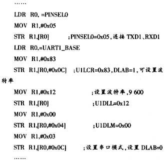
When using UART1, you must first set the TXD1 and RXD1 pin connection methods, and then set the baud rate and working mode of the serial port to send and receive data. This system uses an 11.0592MHz crystal oscillator and is not suitable for PLL and VPB. Divide by 4, set the UART1 baud rate to 9600bit/s, then the divisor value N=18, which is 12H. The initialization procedure of UART1 is as follows: 
In the operating system environment, the serial port will be automatically initialized when the system starts, so the application Calling serial port resources will become easier. It is worth noting that applications are often multiple systems. In order to monitor serial port messages in real time, a separate serial port scanning task is generally opened in the operating environment to ensure that information is not lost. , add the serial port register initialization code in the main function of an existing project file, and add the serial port scanning task. Since the wireless module is controlled by the system GPIO, the scanning program also includes the I/O When the system receives the serial port information, it will actively send a serial port information to the main task. When the main task receives the information, it will call the response function to respond to the message.
7 Conclusion
The wireless communication module nRF401 integrates transmitting and receiving, which greatly simplifies the complexity of lighting controller design. Intelligent lighting controllers can easily be networked through the RS485 interface, which provides convenience for realizing smart home networking.
Previous article:Design and implementation of a liquid crystal display based on DSP control
Next article:LED drive control design based on TPIC6B273
Recommended ReadingLatest update time:2024-11-17 02:55


- Popular Resources
- Popular amplifiers
-
 Mission-oriented wireless communications for cooperative sensing in intelligent unmanned systems
 -
 Semantic Segmentation for Autonomous Driving: Model Evaluation, Dataset Generation, Viewpoint Comparison, and Real-time Performance
 -
 Machine Learning and Embedded Computing in Advanced Driver Assistance Systems (ADAS)
 -
 Electric Vehicle Wireless Battery Management Revolution Has Begun and the ROI Potential Is Huge
- MathWorks and NXP Collaborate to Launch Model-Based Design Toolbox for Battery Management Systems
- STMicroelectronics' advanced galvanically isolated gate driver STGAP3S provides flexible protection for IGBTs and SiC MOSFETs
- New diaphragm-free solid-state lithium battery technology is launched: the distance between the positive and negative electrodes is less than 0.000001 meters
- [“Source” Observe the Autumn Series] Application and testing of the next generation of semiconductor gallium oxide device photodetectors
- 采用自主设计封装,绝缘电阻显著提高!ROHM开发出更高电压xEV系统的SiC肖特基势垒二极管
- Will GaN replace SiC? PI's disruptive 1700V InnoMux2 is here to demonstrate
- From Isolation to the Third and a Half Generation: Understanding Naxinwei's Gate Driver IC in One Article
- The appeal of 48 V technology: importance, benefits and key factors in system-level applications
- Important breakthrough in recycling of used lithium-ion batteries
- Innolux's intelligent steer-by-wire solution makes cars smarter and safer
- 8051 MCU - Parity Check
- How to efficiently balance the sensitivity of tactile sensing interfaces
- What should I do if the servo motor shakes? What causes the servo motor to shake quickly?
- 【Brushless Motor】Analysis of three-phase BLDC motor and sharing of two popular development boards
- Midea Industrial Technology's subsidiaries Clou Electronics and Hekang New Energy jointly appeared at the Munich Battery Energy Storage Exhibition and Solar Energy Exhibition
- Guoxin Sichen | Application of ferroelectric memory PB85RS2MC in power battery management, with a capacity of 2M
- Analysis of common faults of frequency converter
- In a head-on competition with Qualcomm, what kind of cockpit products has Intel come up with?
- Dalian Rongke's all-vanadium liquid flow battery energy storage equipment industrialization project has entered the sprint stage before production
- Allegro MicroSystems Introduces Advanced Magnetic and Inductive Position Sensing Solutions at Electronica 2024
- Car key in the left hand, liveness detection radar in the right hand, UWB is imperative for cars!
- After a decade of rapid development, domestic CIS has entered the market
- Aegis Dagger Battery + Thor EM-i Super Hybrid, Geely New Energy has thrown out two "king bombs"
- A brief discussion on functional safety - fault, error, and failure
- In the smart car 2.0 cycle, these core industry chains are facing major opportunities!
- Rambus Launches Industry's First HBM 4 Controller IP: What Are the Technical Details Behind It?
- The United States and Japan are developing new batteries. CATL faces challenges? How should China's new energy battery industry respond?
- Murata launches high-precision 6-axis inertial sensor for automobiles
- Ford patents pre-charge alarm to help save costs and respond to emergencies
- Download and answer questions to win prizes: Efficient PCB design with Mentor's Xpedition Layout
- The role of GEL files in TMS320C6000 applications
- 2020-5-21-Bone vibration test completed
- Oscilloscope Differential Probe Delay Measurement
- [SAMR21 New Gameplay] 24. Usage of I2C
- AD17 There is a problem with copper laying on a four-layer board
- Static Timing Analysis Basics and Applications
- Cost-effective 0-10V analog signal isolation technology: based on Y capacitor isolation
- HPM6700/6400 display control system (LCD and 2D graphics acceleration unit, LVGL)
- How to use Segger Embedded Studio to develop the HPM6750?

 Mission-oriented wireless communications for cooperative sensing in intelligent unmanned systems


 京公网安备 11010802033920号