An interesting trade-off occurs when you select input filter capacitors for a low-power, offline power supply. You are compromising the capacitor's ripple current rating with the voltage range over which the power supply operates. By increasing the input capacitor, you can get more ripple current while also reducing the supply's operating input voltage range by reducing the voltage drop across the input capacitors. Doing so affects the power supply's transformer turns ratio and various voltage and current stresses. A larger capacitor ripple current rating reduces stress and makes the power supply more efficient.
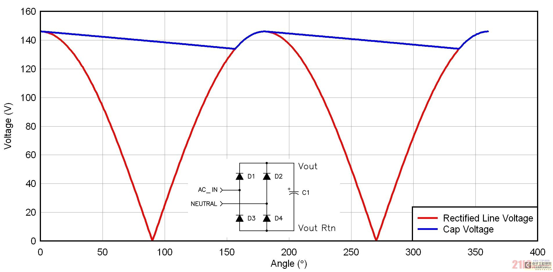
Figures 1 and 2 show two rectifier configurations used in offline power supplies. Figure 1 is a full-wave bridge where the AC input voltage is simply rectified and then fed to the capacitor. This circuit is common in wide range AC and 230 volt AC applications. The capacitor is charged to the peak of the sine wave and then discharged for most of the half cycle. The capacitor ripple current consists of two parts: first the charging period, where the current is determined by the capacitor value and the applied dV/dt, and second the capacitor discharge. The power supply acts as a constant power load, so the capacitor discharges at a nonlinear rate, which is calculated as: W = ½ * C *V^2 = P * dt.

Figure 1. Full-wave bridging used in many offline designs
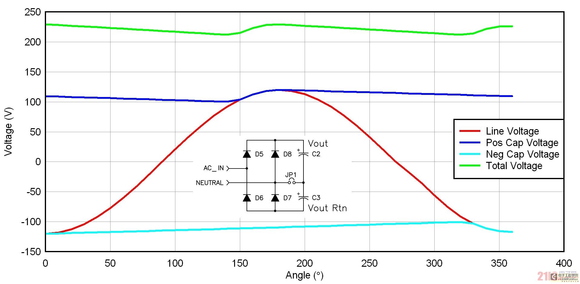
Figure 2 depicts a voltage doubler rectifier configuration that is used in many 115/230 VAC applications. If you have a 230 VAC application, your input stage needs to handle the maximum input voltage (265 VAC) multiplied by the crest factor, which is close to 400 volts. When used with a 115 VAC input, the voltage doubler steps up the rectified voltage to close to the 230 VAC input level. We can reduce the rectified voltage range over which the power supply operates by designing a power supply specifically for 230 VAC line voltage. We usually use a jumper or switch to switch between different rectifier configurations. The only drawback to this approach is that occasionally the 230 VAC input is artificially doubled, wreaking havoc on the power supply. Figure 2 shows some waveforms from the voltage doubler circuit. There is no charge between the capacitors. The two rectifiers alternately apply the input voltage to each capacitor. During one cycle, each capacitor is charged to the peak line voltage, so they each have a line frequency ripple component. Since the capacitors charge out of phase, their sum has a ripple frequency that is twice the line frequency.

Figure 2 Voltage doubler reduces power line voltage range
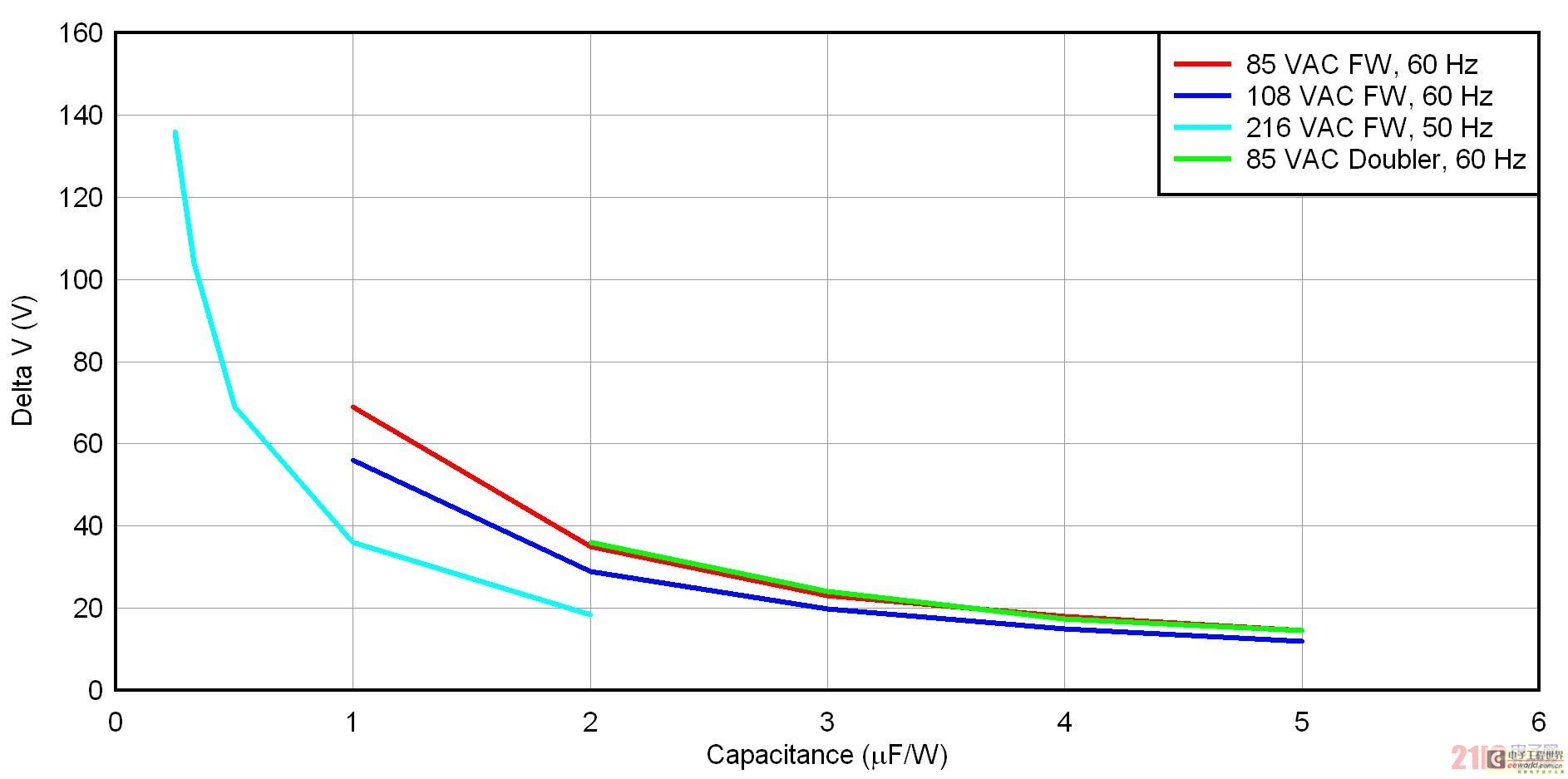
Figure 3 shows the uF/W normalized voltage drop for four rectifier/input voltage methods. There are three full-wave bridge methods for low-line US (108 VAC/60 Hz), low-line Japan (85 VAC/50 Hz), and low-line Europe (216 VAC/50 Hz). There is also a voltage doubler for low-line Japan. For the full-wave bridge, normalization is simply dividing the capacitance by the power. In the voltage doubler, normalization is dividing the capacitance of one of the two series capacitors by the power. To use this graph, first determine your rectifier configuration and choose an acceptable voltage drop. After that, you simply read the uF/W of the input capacitance. Finally, de-normalize by multiplying by your power.

Figure 3 Large capacitors can reduce the input line voltage range and improve efficiency
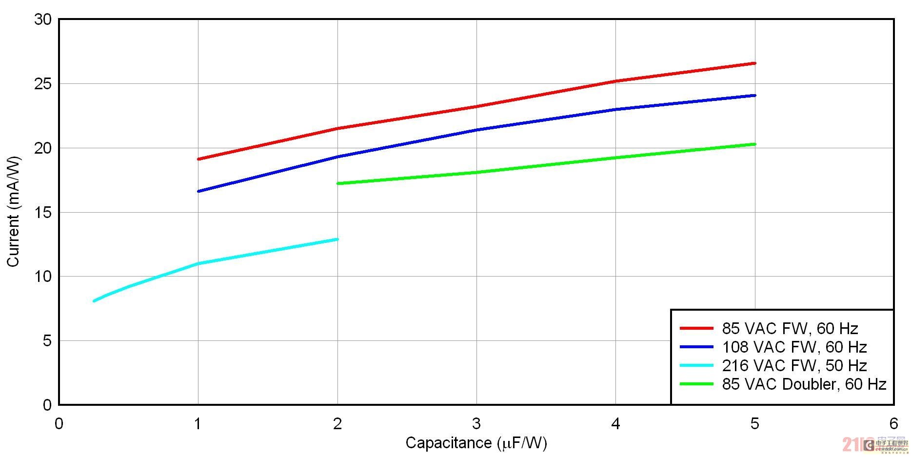
You can then use Figure 4 to calculate the ripple current rating of the capacitor. Figure 4 shows the normalized ripple current versus normalized input capacitance. Interestingly, the ripple current is not closely related to the capacitance. This is because during discharge, the current is determined by a nearly constant current from the load. Only during the charging cycle is the current very different. This occurs when the asymptotic ripple current increases as the capacitance (uF/W) decreases. The peak current is higher for larger capacitance and smaller conduction angles. Note that this graph includes only the line frequency ripple current and does not include the effects of high-frequency power supply ripple current.

Figure 4 Increasing uF/W will not significantly increase the input capacitor ripple current
In summary, it is important for the designer to make some compromises when selecting the input capacitor and rectifier configuration. If a full-wave bridge is chosen for a wide range application, the power supply may need to operate over a 4:1 input range. If the designer chooses to use a voltage doubler in the design to reduce this range, there is a risk of overvoltage due to user error. By selecting the correct input capacitor based on the curves provided in this article, the operating voltage range can be limited to a certain extent. Next time, we will discuss an inexpensive power supply protection latch circuit, so stay tuned.
Previous article:Analysis of circulating current in parallel operation of double reverse star rectifier circuits
Next article:Calculation of short-circuit current of ultra-high power rectifier
- Popular Resources
- Popular amplifiers
- MathWorks and NXP Collaborate to Launch Model-Based Design Toolbox for Battery Management Systems
- STMicroelectronics' advanced galvanically isolated gate driver STGAP3S provides flexible protection for IGBTs and SiC MOSFETs
- New diaphragm-free solid-state lithium battery technology is launched: the distance between the positive and negative electrodes is less than 0.000001 meters
- [“Source” Observe the Autumn Series] Application and testing of the next generation of semiconductor gallium oxide device photodetectors
- 采用自主设计封装,绝缘电阻显著提高!ROHM开发出更高电压xEV系统的SiC肖特基势垒二极管
- Will GaN replace SiC? PI's disruptive 1700V InnoMux2 is here to demonstrate
- From Isolation to the Third and a Half Generation: Understanding Naxinwei's Gate Driver IC in One Article
- The appeal of 48 V technology: importance, benefits and key factors in system-level applications
- Important breakthrough in recycling of used lithium-ion batteries
- Innolux's intelligent steer-by-wire solution makes cars smarter and safer
- 8051 MCU - Parity Check
- How to efficiently balance the sensitivity of tactile sensing interfaces
- What should I do if the servo motor shakes? What causes the servo motor to shake quickly?
- 【Brushless Motor】Analysis of three-phase BLDC motor and sharing of two popular development boards
- Midea Industrial Technology's subsidiaries Clou Electronics and Hekang New Energy jointly appeared at the Munich Battery Energy Storage Exhibition and Solar Energy Exhibition
- Guoxin Sichen | Application of ferroelectric memory PB85RS2MC in power battery management, with a capacity of 2M
- Analysis of common faults of frequency converter
- In a head-on competition with Qualcomm, what kind of cockpit products has Intel come up with?
- Dalian Rongke's all-vanadium liquid flow battery energy storage equipment industrialization project has entered the sprint stage before production
- Allegro MicroSystems Introduces Advanced Magnetic and Inductive Position Sensing Solutions at Electronica 2024
- Car key in the left hand, liveness detection radar in the right hand, UWB is imperative for cars!
- After a decade of rapid development, domestic CIS has entered the market
- Aegis Dagger Battery + Thor EM-i Super Hybrid, Geely New Energy has thrown out two "king bombs"
- A brief discussion on functional safety - fault, error, and failure
- In the smart car 2.0 cycle, these core industry chains are facing major opportunities!
- Rambus Launches Industry's First HBM 4 Controller IP: What Are the Technical Details Behind It?
- The United States and Japan are developing new batteries. CATL faces challenges? How should China's new energy battery industry respond?
- Murata launches high-precision 6-axis inertial sensor for automobiles
- Ford patents pre-charge alarm to help save costs and respond to emergencies
- MaixSense R329 development board Tina system test
- Differences between MSP430 programmer emulator and JTAG, SBW, and BSL interfaces
- Common embedded development systems
- BUCK circuit simulation and experiment
- Is there a dedicated chip for PWM output of I2C interface?
- Compact power management solution
- Welcome to the wonderful world of MicroPython
- 【Arduino】168 Sensor Series Experiments (214) --- 8x32-bit full-color WS2812B screen
- [RVB2601 Creative Application Development] +01 Unboxing and First Experience
- Urgently looking for! Texas Instruments Ti official website accounts registered before 2020 require registration with corporate email!

 Analytical PDN Voltage Ripple Calculation Using


 京公网安备 11010802033920号