In the information age, BP machines have become a commonly used communication tool. At present, the transmitting equipment of my country's BP main station uses imported equipment, with an output voltage of 13.8V and a current of 15~20A. The imported power supply does not have a thyristor part, but my country's power grid fluctuates greatly, so this low-cost regulated power supply is designed. This design adds a thyristor phase control device on the basis of a series feedback regulated regulated power supply. The voltage drop at both ends of the adjustment tube is used to control the conduction angle of the thyristor trigger, keeping the voltage drop of the adjustment tube unchanged. Designed a tracking high-power DC regulated power supply. This regulated power supply limits the power consumption of the adjustment tube and achieves high power.
The regulated power supply is mainly composed of single-phase half-controlled bridge rectifier and filter, linear voltage regulator and thyristor phase control. It is also equipped with over-current protection, short-circuit protection, over-heat protection device and display part. When the voltage of the 220V power grid fluctuates ±15%, the output voltage is 13.8V and the output current can reach 20A. Due to the use of thyristor phase control technology, the voltage drop at both ends of the adjustment tube can be limited to about 3V, and the power consumption is no more than 40W, which improves power efficiency.
When the output current exceeds 20A, current limiting protection can reduce the output current. If the output is short-circuited, the short-circuit protection output blocks the signal and turns off the thyristor. When the temperature of the regulating tube is higher than 60°C, the fan is started, when the temperature is lower than 40°C, the fan is turned off, and when the temperature is higher than 80°C, the thyristor is turned off. The power supply uses an integrated thyristor trigger, dual operational amplifiers and a temperature-compensated voltage regulator tube as the reference source, and is equipped with a three-terminal voltage regulator as an auxiliary power supply to achieve high accuracy.
2 Specific circuit implementation
The circuit structure block diagram is shown in Figure 1.

This circuit uses a one-way bridge half-controlled rectifier circuit to reduce costs. High-power or high-current stabilized power supplies generally use L-C filter circuits. However, high-current filter reactors are large, heavy, and expensive. Therefore, large capacitor filtering is still used in the design of the regulated power supply. The linear regulator part still adopts the principle of series feedback adjustment regulator to form a closed-loop feedback system. It mainly includes: adjustment tube, sampling circuit, reference voltage source, and error comparison amplifier. Since the output current of this regulated power supply is 20A, which is very large, in order to reduce the power consumption of the adjustment tube, a parallel connection is adopted. In this power supply, the adjustment tube is connected in parallel with two high-power triodes, so that the current flowing through each tube is about 10A. . In this way, the power consumption of each tube is no more than 40W, which reduces the power consumption of the adjustment tube. The collector current of the adjustment tube is about 10A, so a high-power transistor should be used, and β=40~50 should be selected. In this way, the base current should reach 2×0.3A, that is, 600mA. The output current of general integrated operational amplifiers is only tens of milliamperes, and the output end of the comparison amplifier circuit cannot directly drive the adjustment tube. Therefore, a push stage is added between the output end of the comparison amplifier circuit and the base of the adjustment tube. Choose a low-power triode to form a composite tube. The starting resistor R c is 2k. The anti-vibration capacitor C is 10μF.
In the voltage stabilizing circuit, the reference source is the reference for the operation of the entire voltage stabilizing system, and the final effect of voltage stabilization depends on the level of the reference source. Therefore, in this power supply, the 2CW234 series silicon voltage regulator tube with temperature compensation characteristics is selected as the reference source, and its stable voltage is selected to be 6.4V. It is powered by a three-terminal integrated voltage regulator with good characteristics, and the current limiting resistor adopts a precision metal film resistor R (temperature coefficient is about ±1×10 -5 /℃). In order to reduce the impact of noise, the voltage regulator tube is packaged in a small container containing oil, and the noise indicators will be significantly improved.
Voltage sampling is shown in Figure 2. Divide the collector-emitter voltage of the adjustment tube through resistors, and send the divided emitter voltage to the inverting end of the comparison amplifier through a resistor; add a voltage regulator tube in series to the collector voltage sampling circuit. This pipe determines the size of the pressure drop in the adjustment pipe. Select 3.3V here. After subtracting the voltage regulator value from the collector voltage, the divided voltage is sent to the non-inverting terminal of the comparison amplifier. In order to ensure the sampling accuracy, the collector-emitter sampling resistor should be completely symmetrical, and precision metal film resistors of the same model with good temperature characteristics should be selected. The comparison amplifier uses an integrated operational amplifier and is connected to negative feedback.

Let R 1 = R 3 , R 2 = R 4 ; set the voltage division coefficient n = R 2 / (R 1 + R 2 ); the output of the integrated operational amplifier is U o ; the amplification coefficient is K; the collector voltage of the adjustment tube is U C ;The voltage at the emitter of the adjusting tube is U E ; the voltage at point A is U A ; the voltage at point B is U B ; there are:

When the voltage drop of the regulating tube increases, U cE rises, causing U o to increase, that is, the control voltage U b of the flip-flop increases. However, the integrated flip-flop KJ785 is a negative type: the control voltage increases and the conduction angle decreases. Therefore, the trigger pulse moves backward and the rectified output decreases.
The silicon controlled rectifier is responsible for the first step of voltage stabilization, and the change in its output voltage is determined by the change in conduction angle. The phase control part changes the thyristor conduction angle based on the change in the voltage drop of the adjustment tube, thereby changing the output voltage of the rectifier filter circuit and maintaining the voltage drop of the adjustment tube at about 3V. In this regulated power supply, KJ785 thyristor phase-shift trigger circuit is used. Because as a power supply product, it should strive to have good device performance, simple circuit, and easy implementation on the premise of realizing the same function. The trigger circuit can output two trigger pulses with a phase difference of 180 degrees, can shift the phase in the range of 0 to 180 degrees, and can be used to control single-phase, bidirectional thyristors and transistors.
KJ785 is composed of synchronous detection register circuit, reference power supply, sawtooth wave forming circuit, phase-shift voltage and sawtooth wave comprehensive comparison circuit and logic control power amplification. The slope of the sawtooth wave is determined by the external resistor connected to pin 9 and the external capacitor connected to pin 10. The pulse width is determined by the external capacitor of the pin. When the capacitor is not connected, the pulse width is determined by the internal capacitor, which is about 30μs.
KJ785 only needs a single power supply to operate, and the trigger circuit is negative polarity, that is, the phase-shift voltage increases and the conduction angle decreases. The synchronous voltage is input from pin 5, which can be taken directly from the grid voltage. The step-down current limiting resistor takes the grid voltage × 10 3 Ω, or a synchronous transformer can be used to isolate the input. Pins 7 and 6 provide control terminals for pulse train and pulse blocking.
The functions of each pin are shown in Table 1.

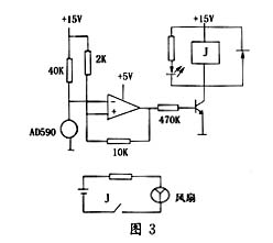
The circuit is shown in Figure 3.
External characteristics of AD590: at 0℃, its current is 273μA; for every 1℃ temperature rise, the current increases by 1μA; for every 1℃ drop in temperature, the current decreases by 1μA; the operating temperature is -50℃~+150℃; in order to avoid the comparator frequently Action or malfunction, select the hysteresis width to be 1V.


Take R=40kΩ; choose the integrated operational amplifier to be powered by a single power supply +5V, which can be obtained by dividing the voltage by CW78M15.
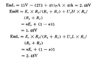
Assuming that the comparator reference voltage is EmH when the temperature is 65°C, there is:

Assuming that the comparator reference voltage is EmL when the temperature is 40°C, we have


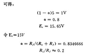
Take: R 1 =2k; R f =10k
Verification:

So: when the temperature is 61℃, start the fan; when it drops to 40℃, turn off the fan. When the temperature of the regulating tube reaches about 80°C, the comparator outputs zero level, turns off the thyristor, and then turns off the circuit.
In this regulated power supply, the short-circuit protection function is to determine a short circuit when the output voltage is detected to be lower than 2V and delayed for 2 seconds. Send a blocking signal to turn off the thyristor and shut down the circuit to prevent damage to the device.
The function of the current limiting protection is to reduce the base current of the adjustment tube when the load current exceeds 20A, thereby reducing the output current.
3 Conclusion:
This new type of tracking silicon-controlled DC voltage stabilized power supply has low cost, good performance and high precision, and is suitable for use in BP transmitter stations. The output voltage range can reach 12V to 15V, and the current can reach 20A. The characteristic part of this power supply is the phase control, which combines the advantages of a thyristor and a series feedback regulator, overcoming the shortcomings of excessive power consumption of the regulating tube in the traditional series feedback regulated regulated power supply.
references
1 Qu Xueji, Wang Zengfu, Qu Jingkai. Practical manual for stable power supply. Beijing: Electronic Industry Press, 1994.11
2 Wu Runyu, Xuan Yinhua, Miao Yinmei, Zhou Gongkai. Practical and stable power supply. Beijing: People's Posts and Telecommunications Press, 1994.5
3 Zhao Xuequan, Zhang Guohua. Power circuit. Beijing: Electronic Industry Press, 1995.3
4 Xue Xueming, Wang Zhihong. Stable power supply and its circuit example. China Railway Press, 1990.7
5 Shi Yu, Li Shuxian, Wang Wenyu. Power electronics technology examples and circuit design guidance. Beijing: Machinery Industry Press, 1999.5
6 Zhang Ankang, Tan Xilin. Technical Manual for Electronic Engineers. Nanjing: Jiangsu Science and Technology Press, 1993.4
7 Wang Changfu, Gu Zhenqiu, Wu Da. Practical handbook of small power transistors at home and abroad (domestic volume). Beijing: Electronic Industry Press, 1994
8 Wang Qiying. SCR power supply. Beijing: People's Posts and Telecommunications Press, 1984.6
9 Yan Meihui, Yang Guangbi. Analysis and application of integrated operational amplifier. Beijing: Electronic Industry Press, 1992.5
10 Ji Gang, Wu Qinqin, Gu Shengyuan. Principle and maintenance of digital display adjustment instrument. Shanghai: East China Institute of Chemical Technology Press, 1992.5
11 Wen Xinyi. A collection of selected practical electronic production. Beijing: Electronic Industry Press, 1996.3
12 PCSEN. Power Electronics Data.McGraw-HillPublishing Company Limited, 1993
Previous article:Touch electrical switch circuit
Next article:Development of a current-mode DC/DC converter
- Popular Resources
- Popular amplifiers
- MathWorks and NXP Collaborate to Launch Model-Based Design Toolbox for Battery Management Systems
- STMicroelectronics' advanced galvanically isolated gate driver STGAP3S provides flexible protection for IGBTs and SiC MOSFETs
- New diaphragm-free solid-state lithium battery technology is launched: the distance between the positive and negative electrodes is less than 0.000001 meters
- [“Source” Observe the Autumn Series] Application and testing of the next generation of semiconductor gallium oxide device photodetectors
- 采用自主设计封装,绝缘电阻显著提高!ROHM开发出更高电压xEV系统的SiC肖特基势垒二极管
- Will GaN replace SiC? PI's disruptive 1700V InnoMux2 is here to demonstrate
- From Isolation to the Third and a Half Generation: Understanding Naxinwei's Gate Driver IC in One Article
- The appeal of 48 V technology: importance, benefits and key factors in system-level applications
- Important breakthrough in recycling of used lithium-ion batteries
- Innolux's intelligent steer-by-wire solution makes cars smarter and safer
- 8051 MCU - Parity Check
- How to efficiently balance the sensitivity of tactile sensing interfaces
- What should I do if the servo motor shakes? What causes the servo motor to shake quickly?
- 【Brushless Motor】Analysis of three-phase BLDC motor and sharing of two popular development boards
- Midea Industrial Technology's subsidiaries Clou Electronics and Hekang New Energy jointly appeared at the Munich Battery Energy Storage Exhibition and Solar Energy Exhibition
- Guoxin Sichen | Application of ferroelectric memory PB85RS2MC in power battery management, with a capacity of 2M
- Analysis of common faults of frequency converter
- In a head-on competition with Qualcomm, what kind of cockpit products has Intel come up with?
- Dalian Rongke's all-vanadium liquid flow battery energy storage equipment industrialization project has entered the sprint stage before production
- Allegro MicroSystems Introduces Advanced Magnetic and Inductive Position Sensing Solutions at Electronica 2024
- Car key in the left hand, liveness detection radar in the right hand, UWB is imperative for cars!
- After a decade of rapid development, domestic CIS has entered the market
- Aegis Dagger Battery + Thor EM-i Super Hybrid, Geely New Energy has thrown out two "king bombs"
- A brief discussion on functional safety - fault, error, and failure
- In the smart car 2.0 cycle, these core industry chains are facing major opportunities!
- The United States and Japan are developing new batteries. CATL faces challenges? How should China's new energy battery industry respond?
- Murata launches high-precision 6-axis inertial sensor for automobiles
- Ford patents pre-charge alarm to help save costs and respond to emergencies
- New real-time microcontroller system from Texas Instruments enables smarter processing in automotive and industrial applications
- [GD32450I-EVAL] Unpack and power on to build a development environment
- 【Drawing board experience】 PCB design skills of switching power supply
- The history and concept of radio and its key technologies
- Help
- Failed experience of using BlueNRG-1 to make a BLE chicken-eating tool
- Exploiting software vulnerabilities! 19-year-old boy remotely hacked into Tesla
- Gizwits GoKit 3 Hardware Manual
- TMS320C6678 ZYNQ Dual-core ARM Communication Case Development Manual - matrix_multiply Case
- Monochrome screen upgrade: How to quickly upgrade the DWIN T5UIC1 color screen
- Intelligent management tools used by power operation and maintenance personnel

 Circuit Intuition
 CVPR 2023 Paper Summary: Robotics
 TL064BCJ


 京公网安备 11010802033920号