The advancement of LED technology has provided new opportunities for the design of automotive headlights, and high-power white LEDs have gradually become a new light source for automotive headlights.
At the same time, various optical systems suitable for LED light sources have also appeared one after another. In the projection type LED car headlight system, aspheric lenses are commonly used as projection lenses. However, for large aperture lighting systems, if general spherical or aspheric lenses are used, their volume and mass will be quite large, and the cost will be greatly increased. Fresnel lens is a kind of aplanatic lens with light weight and relatively large aperture. It can effectively reduce the thickness of the lens by "suppressing" the traditional lens. Fresnel lens is mainly used for focusing and collimation. Its most significant advantage is the ability to collect light. In addition, it is thin, light, low cost, easy to make, and replaceable. It is widely used in various fields, such as overhead projectors, solar concentrators, car headlights, etc.
At present, the design of dense-grained Fresnel lens (with annular band width not exceeding 0.5 mm) is to regard the annular band surface as a conical surface, and better design results can be obtained using existing optical design software, such as CODEV or Zemax. The sparse-grained Fresnel lens regards the annular band surface as a spherical surface, and determines the radius of curvature of each annular band surface according to the design parameters. However, this design only traces specific light rays to determine the structure of the Fresnel lens. For these specific light rays, spherical aberration can be eliminated, but for the rest of the light rays passing through the spherical surface, spherical aberration still exists. Therefore, for Fresnel lenses with large pitch, the usual method of designing Fresnel lenses is no longer applicable.
A new design scheme of large pitch and equal thickness Fresnel aspheric lens is proposed, and the surface shape of the ring zone is designed to be aspheric. According to Snell's law and Fermat's principle, the equal optical path design method is adopted. The general expression of each ring zone surface shape is derived by tracing the edge light and any light of the ring zone surface, so that it can reflect the relationship between various parameters. The numerical solution of the surface shape is obtained by MATLAB, and the non-working surface structure of the lens is determined according to the given parameters. The design compares the performance of Fresnel aspheric lens and aspheric lens in light distribution under the same conditions. The simulation results show that in the projection LED car headlight system, large pitch and equal thickness Fresnel aspheric lens is not only feasible, but also has better performance.
1 Design theory and method
The thickness of a large pitch Fresnel lens is generally large. If an equidistant design is adopted, it will be thin in the middle and thick at both ends, which will easily lead to an unstable mechanical structure, as shown in Figure 1. Therefore, an equal thickness design method is adopted. In addition, the discontinuity of the Fresnel lens surface and the "dark area" of the light beam will reduce the brightness of the light source. Therefore, it is necessary to optimize the design of the non-working surface to effectively reduce the mass of the system and minimize the brightness loss.

Figure 1 Typical Fresnel lens
1.1 Design of non-working surface
Different collimation structures have different design requirements for the non-working surface. According to the collimation structure and the principle of minimizing the brightness reduction, the following structure is used for design. Usually, the non-working surface of the Fresnel lens is a cylindrical surface. Figure 2 is a schematic diagram of the non-working surface design. Assuming that the second focus is an imaginary light source O, it emits light A and B, which are emitted in parallel after passing through the Fresnel lens of equal thickness. Light B is the critical light of the i-th ring and the i-1-th ring. It can be seen that the minimum incident angle of the i-th ring is θimin. When the incident angle of the i-th ring is less than θimin, the light is refracted by the i-1-th ring aspherical surface and emitted in parallel. It can be determined that the part surrounded by CDE can be cut off because it does not actually play a refractive role. Therefore, the non-working surface can be designed as an aspherical surface. Assuming that the inclination angle of the non-working surface at this time is δimin, the refractive index of the lens is n, and Snell's law can be obtained:

As the number of rings i increases, θimin also increases, and δimin also increases. Because ∠DCE=δimin, the inclination angle ∠DCE of the hypotenuse also increases. Finally, it can be seen that as the number of rings increases, more and more parts will be cut off, and the actual annular surface of the refracted light will become smaller and smaller.
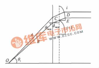
Figure 2 Design of non-working surface
1.2 Design of working surface
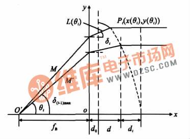
Figure 3 Schematic diagram of large pitch Fresnel aspheric lens design
As shown in Figure 3, assume that a hypothetical light source is on the axis of the Fresnel lens:
The light rays M and M′ emitted from point O′ are refracted by the Fresnel lens and emitted in parallel. A coordinate system is established with point O as the origin. Point Pi is the intersection of the emitted light rays of the ith ring (i≥1) and the ring zone surface. Let the coordinates of point Pi be (x(θi), y(θi)), which are all functions of θi. d0 is the thickness of the substrate.
According to Snell's law:

For light rays M, M′ and the central light ray, according to Fermat’s principle:

Where: n is the refractive index of the lens; θi and δi are the angle of incidence and angle of refraction of the base plane of the i-th ring respectively; di is the distance from the vertex of the lens to the vertex of the central ring lens when the i-th ring is completed as an aspherical lens; d is the thickness of the lens; θ(i-1)max is the maximum angle of incidence of the i-1th ring; L(θi) is the length of the light in the lens; fB is the distance from the light source to the base plane, that is, the back intercept. At this time, the coordinates of point Pi are:

Using the equal thickness condition:

but:

When i = 1, let θ0max = 0, which includes the central ring. Let x(θi) = d0, find the maximum incident angle θimax corresponding to the ith ring, and substitute it into y(θimax) to get the semi-aperture of the ith ring.
It can be seen from formula (5) that the aperture y (θi) of each ring is related to the lens thickness d, back intercept fB, material refractive index n, etc. In order to determine the size of the aperture, a program can be written in the program to determine whether y (θi) is close to a given aperture to determine the number of rings. In this way, the outline of each ring is constructed by Matlab software, and the solid model is constructed using Tracepro software.
2 System Simulation and Result Analysis
Using formula (5), an equal-thickness Fresnel aspheric lens with a back focus of 15 mm, a substrate thickness of 2 mm, and a pitch thickness of 3 mm was designed. PMMA, an optical plastic commonly used in Fresnel lenses, was selected. For D light, the refractive index is 1.491 and the transmittance is 90%~92%. Through calculation, the diameter of the lens is obtained to be 38.5 mm. Figures 4 and 5 are the contours of the equal-thickness Fresnel aspheric lens written by Matlab program.
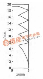
Figure 4: Outline of the shape of an equal-thickness Fresnel aspheric lens
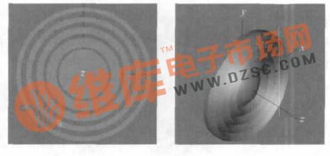
Figure 5 Three-dimensional view of an equal-thickness Fresnel aspheric lens
It is used for the projection lens of the projection type LED automobile headlight, as shown in Figure 6. The light source uses the RebEL model LED of Lumileds to simulate the light source, and the reflector is a multi-ellipsoid reflector. At the same time, for the convenience of comparison, an aspheric lens with a back intercept of 15 mm, a diameter of 38.5 mm, and a thickness of 20.2 mm is designed using Zemax. Five projection modules generate low beams, and when the five modules do not have light baffles, the three reflective modules above generate high beams. The comparison results of the low and high beams of the simulated test screen are shown in Figures 7 to 10.
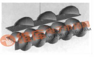
Figure 6 LED projection type car headlight model
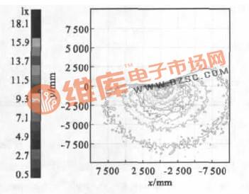
Figure 7 Fresnel aspheric lens low beam illumination diagram
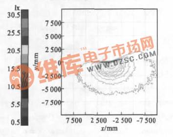
Figure 8 Aspheric lens low beam illumination diagram
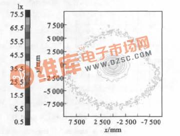
Figure 9 Fresnel aspherical lens high beam illumination diagram
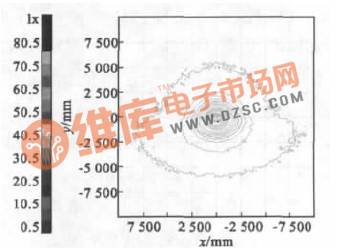
Figure 10 Aspheric lens high beam illumination diagram
By comparing Figure 7 and Figure 8, it can be seen that the Fresnel aspherical lens has a larger extended field of view than the aspherical lens, ensuring a sufficient visible range. Define the horizontal field of view angle:

r1 and r2 are the distances from the center point of the test screen to the left and right edges of the light shape in the horizontal direction, and L is the distance from the lamp to the test screen, which can generally be considered to be 25 m. Through calculation, the field of view of the new lens is 39.5°, which is 4.1° larger than the field of view of the aspherical surface of 35.4°. With a larger field of view, under the same light energy conditions, the distribution will be more gentle, and the gradient change of illumination will be smoother.
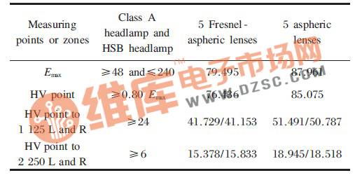
Table 1 and Table 2 are the illumination values of low beam and high beam on the 25m test screen respectively.
Table 1 Low beam illumination limit (unit: lx)
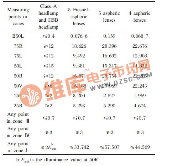
As shown in Table 1, under the same conditions, only the projection lens is changed, and the use of 5 Fresnel aspheric lens modules can well meet the requirements of the regulations. With 5 aspheric lenses, the overall illuminance values have increased, but the illuminance values at the two test points of 75 L and 50 L exceed the limits required by the regulations. In order to reduce the illuminance value, considering the situation of 4 modules, it can be seen that the illuminance value at the 75 L point still exceeds the specified limit, while the illuminance value at the 25 L point is slightly lower than the specified limit, which shows that the aspheric lens cannot disperse the light energy evenly, and it is very concentrated in the hot zone while the edge distribution is very small. The new lens effectively disperses the light energy, so that there is enough light energy in the central hot zone, and the edge can also meet the requirements. In terms of glare, the regulations stipulate that the part above the cutoff line is the glare area, and the B50 L test point is a test point for quantitatively describing the glare. The smaller the value of this point, the better. Although both lenses meet the requirements, compared with the aspheric lens, the new lens has a smaller value, which is more conducive to reducing the impact of glare.
For high beam, as shown in Table 2, both lenses can meet the regulatory requirements. The overall illumination value of the Fresnel aspheric lens has decreased, which is mainly due to the wide divergence of the light, so that part of the energy cannot be projected onto the test screen. However, as can be seen from Figures 9 and 10, the Fresnel aspheric lens has a larger projection range, which is more conducive to the judgment of the oncoming vehicle by the other driver.
Table 2 High beam illuminance limit (unit: lx)
In terms of the system's size and structure, the thickness of the new lens is 15.2 mm smaller than that of the aspheric lens, which reduces the depth of the system and is beneficial to the installation of car headlights. It also reduces the mass of the system and provides more flexible and convenient design freedom for the styling of car headlights.
3 Conclusion
The aspheric lens is replaced by a new type of large pitch and equal thickness Fresnel aspheric lens. The surface formula of the lens is obtained through the law of geometric optics, and the lens model is constructed using design simulation software. It is put into the LED headlamp system for simulation and comparison. The analysis of the near and far beams shows that it is completely feasible to use this lens as a projection lens for projection-type LED headlights. It has better performance than aspheric lenses in terms of anti-glare, extended field of view and structural size. This design method can be widely used in the design of Fresnel collimation elements in large collimation systems.
Previous article:Semtech SC5010 Ultra-thin Notebook Phase-Shifted 8-Channel White LED Backlight Driver Solution
Next article:Protection measures for LED drive circuit
Recommended ReadingLatest update time:2024-11-16 20:35


- Popular Resources
- Popular amplifiers
- MathWorks and NXP Collaborate to Launch Model-Based Design Toolbox for Battery Management Systems
- STMicroelectronics' advanced galvanically isolated gate driver STGAP3S provides flexible protection for IGBTs and SiC MOSFETs
- New diaphragm-free solid-state lithium battery technology is launched: the distance between the positive and negative electrodes is less than 0.000001 meters
- [“Source” Observe the Autumn Series] Application and testing of the next generation of semiconductor gallium oxide device photodetectors
- 采用自主设计封装,绝缘电阻显著提高!ROHM开发出更高电压xEV系统的SiC肖特基势垒二极管
- Will GaN replace SiC? PI's disruptive 1700V InnoMux2 is here to demonstrate
- From Isolation to the Third and a Half Generation: Understanding Naxinwei's Gate Driver IC in One Article
- The appeal of 48 V technology: importance, benefits and key factors in system-level applications
- Important breakthrough in recycling of used lithium-ion batteries
- Innolux's intelligent steer-by-wire solution makes cars smarter and safer
- 8051 MCU - Parity Check
- How to efficiently balance the sensitivity of tactile sensing interfaces
- What should I do if the servo motor shakes? What causes the servo motor to shake quickly?
- 【Brushless Motor】Analysis of three-phase BLDC motor and sharing of two popular development boards
- Midea Industrial Technology's subsidiaries Clou Electronics and Hekang New Energy jointly appeared at the Munich Battery Energy Storage Exhibition and Solar Energy Exhibition
- Guoxin Sichen | Application of ferroelectric memory PB85RS2MC in power battery management, with a capacity of 2M
- Analysis of common faults of frequency converter
- In a head-on competition with Qualcomm, what kind of cockpit products has Intel come up with?
- Dalian Rongke's all-vanadium liquid flow battery energy storage equipment industrialization project has entered the sprint stage before production
- Allegro MicroSystems Introduces Advanced Magnetic and Inductive Position Sensing Solutions at Electronica 2024
- Car key in the left hand, liveness detection radar in the right hand, UWB is imperative for cars!
- After a decade of rapid development, domestic CIS has entered the market
- Aegis Dagger Battery + Thor EM-i Super Hybrid, Geely New Energy has thrown out two "king bombs"
- A brief discussion on functional safety - fault, error, and failure
- In the smart car 2.0 cycle, these core industry chains are facing major opportunities!
- The United States and Japan are developing new batteries. CATL faces challenges? How should China's new energy battery industry respond?
- Murata launches high-precision 6-axis inertial sensor for automobiles
- Ford patents pre-charge alarm to help save costs and respond to emergencies
- New real-time microcontroller system from Texas Instruments enables smarter processing in automotive and industrial applications
- Misalignment issues between 3D packaging and planar packaging
- EEWORLD University Hall ----Embedded Systems and Experiments Xiamen University
- Storage DDR SAMSUNG MICRON
- [Review of SGP40] + Testing the sensor I2C communication with Arduino
- Analysis of the causes of high temperature failure of DCDC power modules
- Near Field Communication (NFC) Transceiver Reference Design
- In electromagnetic field simulation, what are the advantages and disadvantages of FDTD and FEM algorithms?
- Combining 51 code to analyze the programming ideas of RFID card reader
- X-NUCLEO-IKS01A3 sensor driver transplantation based on STM8S-DISCOVERY
- TMDSEVM572X development board link emulator

 Siemens PLC Project Tutorial
 LED Cube Code
 ESP32-S3 source code


 京公网安备 11010802033920号