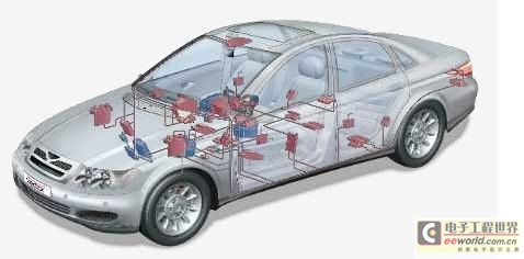
We are experiencing the rapid development of digital signal processing technology and wireless communication technology, which has brought unprecedented changes to the automotive electronics industry. Rohde & Schwarz has played a leading role in this market. Almost all leading automakers in the world are using Rohde & Schwarz's test and measurement technology. System testing includes three major parts: testing the vehicle's infotainment system (
R&S
's
ATSI
system), safety and assistance systems, and electromagnetic compatibility testing. Domestic joint ventures and some local brands are also gradually catching up. For example, almost all of FAW's high-end models use
the
ATSI
system.
Keywords:Test
Reference address:Automotive electronics overall test solution
In the past decade, Rohde & Schwarz has applied its comprehensive patented technology to the communication equipment testing of today's cars. At the same time, Rohde & Schwarz cooperates with well-known chip manufacturers to test chips for automotive electronics, such as the tire pressure monitoring system developed in cooperation. In addition, many suppliers of automotive electronic equipment in the world have chosen Rohde & Schwarz's
PCI
test platform
TSVP
to perform batch testing on automotive electronic modules. For example, some test
systems can complete
comprehensive circuit and function testing of
1.6
million modules per year, including seats, doors, steering wheels composed of heating and drive systems, as well as corresponding display and control components.
Here we will focus on a small solution for automotive electronic bus testing. Since it is applied on an oscilloscope, the overall solution is very intuitive and easy to understand.


Most automotive electronic buses are CAN and LIN buses, and some high-end models use FlexRay. In terms of speed, the latter is faster and is mainly used in high-end models such as BMW. Since the German BOSCH company invented the CAN bus, it has been widely used in automobiles and various means of transportation due to its reliable communication and low cost, and even in some aerospace fields. The speed is generally within 1M, and the bus frame structure is not complicated. CAN nodes share the bus and negotiate freely between nodes. ECUs (electronic control units) send and receive CAN signals according to the designed algorithm, coordinating the communication and priority between various structural units.

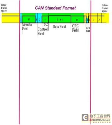
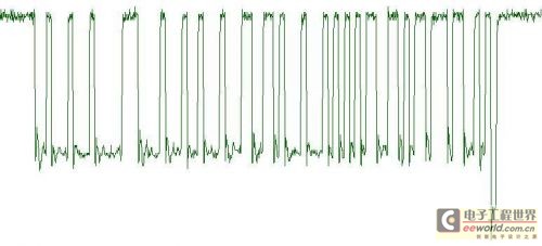
The frame structure is relatively simple, mainly including identification area, control area, data area, check area, and ACK response area. From the actual application, in the process of automotive electronics development, physical layer signals need to be evaluated in many occasions. Due to the judgment of error frames and the location of errors, it is usually necessary to collect the original signal. With the help of special triggering methods, this set of oscilloscopes takes all the needs into consideration.


1.
Trigger
For example, data frames, error frames, remote frames, and specific data bits in the frame structure may all be called trigger conditions to capture the frames we need or are interested in.
Second,
decoding
The decoding process is relatively simple and intuitive. The CAN
physical layer analog signal is decoded into the protocol layer data represented by hexadecimal. Different color areas distinguish different fields of the data frame, and the error frame type is identified and marked. These are all displayed and refreshed in real time on the oscilloscope.
3.
Measurement
For the measurement of CAN signals, it is more about timing measurement, which can quickly understand the timing relationship of CAN signals. With the help of the parameter statistics function of the oscilloscope itself, the trend statistics of bus parameters can be performed to determine the stability of the parameters. Ensure the result measurement of the bus and exclude potential faults from the design.
In short, for automotive electronic bus testing, physical layer signal capture and signal quality analysis are not difficult for oscilloscopes. The difficulty lies in how to find the corresponding design fault from the signal fault, and often if you treat the symptoms but not the root cause, you cannot solve the fundamental problem. The overall solution of automotive electronics, the coordinated debugging and observation of the three major systems of safety and assistance systems, infotainment systems, and electromagnetic compatibility can thoroughly create a safe, stable, and comfortable vehicle electronic system.
Previous article:Introduction to Alpha and Beta Testing
Next article:Electronic load and its application in testing equipment
Recommended ReadingLatest update time:2024-11-16 23:57
Analysis of keys in 2440test
Here we analyze 4 buttons, ENIT8 and EINT19 are missing, but the principle is the same.
4 buttons,
EINT11 / GPG3
EINT13 / GPG5
EINT14 / GPG6
EINT15 / GPG7
external pull-up resistors.
EINT 8-23 share the same IRQ vector.
Initialization step
1, set the IO function, 00 input 01 output 02 The second function
[Microcontroller]
Recommended Content
Latest Test Measurement Articles
- Keysight Technologies Helps Samsung Electronics Successfully Validate FiRa® 2.0 Safe Distance Measurement Test Case
- From probes to power supplies, Tektronix is leading the way in comprehensive innovation in power electronics testing
- Seizing the Opportunities in the Chinese Application Market: NI's Challenges and Answers
- Tektronix Launches Breakthrough Power Measurement Tools to Accelerate Innovation as Global Electrification Accelerates
- Not all oscilloscopes are created equal: Why ADCs and low noise floor matter
- Enable TekHSI high-speed interface function to accelerate the remote transmission of waveform data
- How to measure the quality of soft start thyristor
- How to use a multimeter to judge whether a soft starter is good or bad
- What are the advantages and disadvantages of non-contact temperature sensors?
MoreSelected Circuit Diagrams
MorePopular Articles
- Innolux's intelligent steer-by-wire solution makes cars smarter and safer
- 8051 MCU - Parity Check
- How to efficiently balance the sensitivity of tactile sensing interfaces
- What should I do if the servo motor shakes? What causes the servo motor to shake quickly?
- 【Brushless Motor】Analysis of three-phase BLDC motor and sharing of two popular development boards
- Midea Industrial Technology's subsidiaries Clou Electronics and Hekang New Energy jointly appeared at the Munich Battery Energy Storage Exhibition and Solar Energy Exhibition
- Guoxin Sichen | Application of ferroelectric memory PB85RS2MC in power battery management, with a capacity of 2M
- Analysis of common faults of frequency converter
- In a head-on competition with Qualcomm, what kind of cockpit products has Intel come up with?
- Dalian Rongke's all-vanadium liquid flow battery energy storage equipment industrialization project has entered the sprint stage before production
MoreDaily News
- Allegro MicroSystems Introduces Advanced Magnetic and Inductive Position Sensing Solutions at Electronica 2024
- Car key in the left hand, liveness detection radar in the right hand, UWB is imperative for cars!
- After a decade of rapid development, domestic CIS has entered the market
- Aegis Dagger Battery + Thor EM-i Super Hybrid, Geely New Energy has thrown out two "king bombs"
- A brief discussion on functional safety - fault, error, and failure
- In the smart car 2.0 cycle, these core industry chains are facing major opportunities!
- The United States and Japan are developing new batteries. CATL faces challenges? How should China's new energy battery industry respond?
- Murata launches high-precision 6-axis inertial sensor for automobiles
- Ford patents pre-charge alarm to help save costs and respond to emergencies
- New real-time microcontroller system from Texas Instruments enables smarter processing in automotive and industrial applications
Guess you like
- Registration for STMicroelectronics Chengdu Industrial Tour is now open! ST fans are sincerely invited to walk the streets of Chengdu!
- Visual operation makes sound more intuitive
- RFID distance-coupling type
- New uses for old mobile phones (5) - Install KeDao Cloud
- 「Power amplifier experiment case」Application of ATA-2161 high voltage amplifier in lossless transportation
- "Dry Goods" PCB design tips, how to quickly adjust the silk screen and trim the line (I am a porter)
- [Practical Book] Full-color illustrations of electrical technology and skills
- Read to get a gift | Do you know, do you know, there should be more car solutions!
- [Sipeed LicheeRV 86 Panel Review] 3. Image Burning Test
- Micropython wireless device command line tool upydev

 Real-time driver monitoring system via modal and viewpoint analysis
 CVPR 2023 Paper Summary: Robotics


 京公网安备 11010802033920号