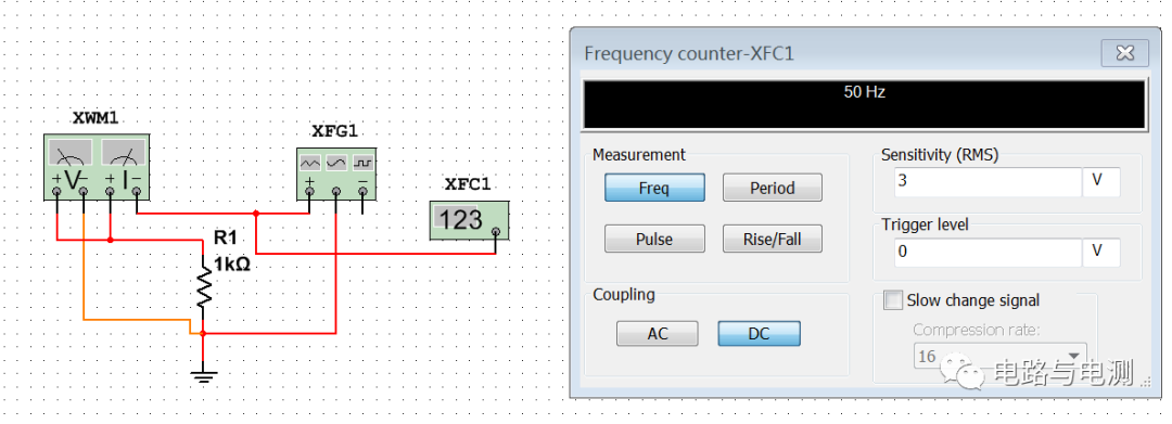
Frequency meters can measure parameters such as frequency, period and pulse width of periodic signals. This section introduces the use of Multisim's virtual frequency meter.
1) Place the frequency meter on the working platform
Place the mouse under the multimeter icon on the right border of the workbench and select the icon until "Frequency Counter" is displayed. This is a virtual frequency meter. The operating steps are the same as for a multimeter. Click this icon to pick up the instrument. Click the left mouse button again on the appropriate position of the working platform to place the frequency meter at this position.
Frequency meter use
There is only one terminal button on the frequency meter icon. Connect it to the signal source "+". After clicking the "Run" button, double-click the frequency meter icon XFC1 to open the frequency meter panel, as shown in Figure 1. The measured frequency value is displayed in the black box above the panel.

Figure 1 Frequency meter usage
There are 4 buttons on the lower left side of the display box: "Freq", "Period", "Pulse", and "Rise/Fall". Press the "Freq" and "Period" buttons, and the frequency and period of the measured signal will be displayed in the display box respectively. Press the "Pulse" button, and the display box displays the width of the positive and negative pulses of the measured signal. Because the signal source in this example outputs a 50Hz sine wave signal with a period of 20ms, and the positive and negative half-cycles are equal in length, so pressing this key will display that both the positive and negative half-cycles are 10ms. "Rise/Fall" displays the measured rising and falling edge times of the pulse signal.
On the lower right side of the display box are the input sensitivity and trigger level settings, as well as slow-changing signals that can be compressed and tested again after increasing the frequency.
There are two buttons "AC" and "DC" on the lower left side of the panel, indicating whether the input coupling method is AC coupling or direct coupling (DC coupling). If "AC" is selected, it is AC coupling, and the DC component of the input signal is shielded; if "DC" is selected, it is direct coupling, and the input signal can contain AC and DC components.
summary:
Frequency meters can measure both frequency and period;
The frequency meter has a single-ended input and does not require grounding.
Previous article:The use of virtual volt-ampere characteristic grapher in Multisim
Next article:Use of virtual power meter in Multisim
- Popular Resources
- Popular amplifiers
- Seizing the Opportunities in the Chinese Application Market: NI's Challenges and Answers
- Tektronix Launches Breakthrough Power Measurement Tools to Accelerate Innovation as Global Electrification Accelerates
- Not all oscilloscopes are created equal: Why ADCs and low noise floor matter
- Enable TekHSI high-speed interface function to accelerate the remote transmission of waveform data
- How to measure the quality of soft start thyristor
- How to use a multimeter to judge whether a soft starter is good or bad
- What are the advantages and disadvantages of non-contact temperature sensors?
- In what situations are non-contact temperature sensors widely used?
- How non-contact temperature sensors measure internal temperature
- LED chemical incompatibility test to see which chemicals LEDs can be used with
- Application of ARM9 hardware coprocessor on WinCE embedded motherboard
- What are the key points for selecting rotor flowmeter?
- LM317 high power charger circuit
- A brief analysis of Embest's application and development of embedded medical devices
- Single-phase RC protection circuit
- stm32 PVD programmable voltage monitor
- Introduction and measurement of edge trigger and level trigger of 51 single chip microcomputer
- Improved design of Linux system software shell protection technology
- What to do if the ABB robot protection device stops
- Detailed explanation of intelligent car body perception system
- How to solve the problem that the servo drive is not enabled
- Why does the servo drive not power on?
- What point should I connect to when the servo is turned on?
- How to turn on the internal enable of Panasonic servo drive?
- What is the rigidity setting of Panasonic servo drive?
- How to change the inertia ratio of Panasonic servo drive
- What is the inertia ratio of the servo motor?
- Is it better for the motor to have a large or small moment of inertia?
- What is the difference between low inertia and high inertia of servo motors?
- Very detailed filter basics
- EEWORLD University Hall----Live Replay: How to solve the challenge of precision timing in ADAS systems
- When will it end? ST is out of stock and it is hard to find a domestic alternative, but the domestic ones are also out of stock...
- 【GD32F307E-START】+connected to UASRT interface power supply
- 【Laser target detector】I2C and SPI
- The inverter outputs a sine wave, so how do we measure the harmonics and waveform distortion of the output voltage?
- MOS tube knowledge
- PCB technology: PROTEL's metal slot method
- [ATmega4809 Curiosity Nano Review] Using MCC to configure TCA
- circuitpy compass

 MCP6V26-EMD


 京公网安备 11010802033920号