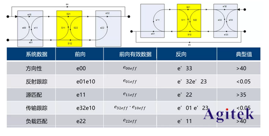
The effective system data characterizes the residual measurement error of the vector network analyzer after calibration. The effective system data index and the network analyzer transmission reflection measurement accuracy are two ways of expressing the same index. If the measurement error and uncertainty of the transmission and reflection measurements obtained through metrological verification meet the network analyzer index, there is no need to measure the effective system data.
For academic research or other purposes, effective system data can be decomposed and calculated from the measurement uncertainty, or it can be measured and calculated using the method described below.
The accurate and effective system data analysis method requires the use of the network analyzer's time domain test mode, using the time gate to obtain the frequency domain value of the relevant reflection peak, and decomposing it to obtain the effective system data. If there is no time domain option and calculation tool software, the ripple method can also be used, which is a simple estimation method for system data.
System effective data definition

Time domain measurement method for system effective data
1/Directivity/Source Matching and Reflection Tracking


2/Load matching
The two ports are directly connected, and S11 and S22 are directly measured, corresponding to the effective load matching in the forward and reverse directions respectively.
3/Transmission tracking
The two ports are directly connected, S21 and S12 are measured, and the ripples are smoothed and removed, corresponding to the effective transmission tracking in the forward and reverse directions respectively.
4/Reflection Tracking
At the port to be tested, such as port 1, connect the calibration device short circuit and open circuit to test S11, reflection tracking
Tr = (S11_Open+S11_Short)/2
System effective data ripple method measurement
When the network analyzer under test does not have the above time domain function, use air line plus load to measure directivity, and use air line plus short circuit to measure source matching. The specific methods are as follows:
Connect the air line and the load (or 20dB mismatcher) to the calibrated port under test. The S11 LinMag curve is as shown in the following figure. Read the peak-to-peak value Mp at the point where the ripple fluctuation is the largest.

Effective directivity = Mpp/2
Connect the air line and the short-circuit breaker to the calibrated port under test. The S11LinMag curve is as shown in the following figure. Read the peak-to-peak value Mpp at the maximum ripple fluctuation.

Source Match = Mpp/(2·Γs)
Previous article:What is the difference between a vector network analyzer and a spectrum analyzer when testing?
Next article:What are the functions of zinc oxide arrester tester
- Popular Resources
- Popular amplifiers
- From probes to power supplies, Tektronix is leading the way in comprehensive innovation in power electronics testing
- Seizing the Opportunities in the Chinese Application Market: NI's Challenges and Answers
- Tektronix Launches Breakthrough Power Measurement Tools to Accelerate Innovation as Global Electrification Accelerates
- Not all oscilloscopes are created equal: Why ADCs and low noise floor matter
- Enable TekHSI high-speed interface function to accelerate the remote transmission of waveform data
- How to measure the quality of soft start thyristor
- How to use a multimeter to judge whether a soft starter is good or bad
- What are the advantages and disadvantages of non-contact temperature sensors?
- In what situations are non-contact temperature sensors widely used?
- LED chemical incompatibility test to see which chemicals LEDs can be used with
- Application of ARM9 hardware coprocessor on WinCE embedded motherboard
- What are the key points for selecting rotor flowmeter?
- LM317 high power charger circuit
- A brief analysis of Embest's application and development of embedded medical devices
- Single-phase RC protection circuit
- stm32 PVD programmable voltage monitor
- Introduction and measurement of edge trigger and level trigger of 51 single chip microcomputer
- Improved design of Linux system software shell protection technology
- What to do if the ABB robot protection device stops
- Huawei's Strategic Department Director Gai Gang: The cumulative installed base of open source Euler operating system exceeds 10 million sets
- Download from the Internet--ARM Getting Started Notes
- Learn ARM development(22)
- Learn ARM development(21)
- Learn ARM development(20)
- Learn ARM development(19)
- Learn ARM development(14)
- Learn ARM development(15)
- Analysis of the application of several common contact parts in high-voltage connectors of new energy vehicles
- Wiring harness durability test and contact voltage drop test method
- Testing of heating power of NOx sensor
- IoT access terminal
- How to Measure Cable Impedance and Loss Using a Vector Network Analyzer
- Make Magazine: Getting started with Python on hardware
- Does the LCD module need to be grounded when used?
- 【BLE 5.3 wireless MCU CH582】11. Mobile app controls the LED on and off
- [Silicon Labs Development Kit Evaluation] + Simplicity Studio V5 environment is successfully built (Win10 environment)
- Registration for the 2021 STM32 National Tour Seminar is now open!
- Flexible use of software to simulate PA parameter changes
- After reading this article, do you have the urge to make some modifications? Let's take a look at the design of an outdoor camera with a temperature switch.

 OP-420GR


 京公网安备 11010802033920号