O Introduction
In the cable production line, it is usually necessary to detect the cable running speed to control the speed of the take-up motor and calculate the length of the cable. The stability of the cabling process parameters is directly related to the quality of wires and cables.
This project is a technical transformation project for a cable factory. The equipment to be transformed is a cable-making machine made using the principle of cable bundles. The transformation content is to replace the entire electrical control system. The pay-off reel of this cable-making machine is fixed, and the take-up reel is fixed on the reel frame to complete the dual movement of twisting and taking up. When working, the cable reel DC motor drives the cable reel to complete the cable taking-up movement, and the cable is neatly arranged on the reel driven by the cable arrangement motor. Driven by the large reel motor, the reel frame is driven by the gear box to achieve axial rotation, and the cable twisting movement is completed, which is the key to ensuring the pitch. The line speed is determined by the rotation speed of the take-up reel. If the speed of the take-up motor is constant, the line speed of the take-up reel will increase as the take-up shaft becomes thicker. Therefore, in order to ensure the constant take-up speed, the speed of the take-up motor should be gradually reduced.
1 System design principle
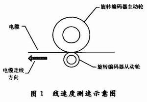
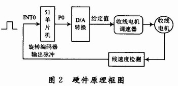
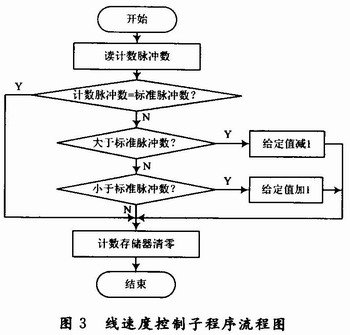
According to the production process requirements of cables, the routing speed of cables of different models is constant. Usually, the running speed of the cable is detected by the cable driving the rotary encoder. The schematic diagram of cable line speed measurement is shown in Figure 1. In this project, the model of the rotary encoder used is the TRDJ1000 series, which outputs 1,000 pulses per rotation. Therefore, according to the number of pulses detected within a certain period of time, the routing speed of the cable can be calculated. In practical applications, it is measured with a rotary encoder with extremely high processing accuracy and a circumference of 500 mm. The driving wheel is coaxially installed with the rotary encoder, and the driving wheel is in contact with the cable. During the cable production movement, the measuring wheel is rotated by friction, so that the linear displacement (length) of the cable is converted into a pulse digital signal output of the rotary encoder. Assume that the number of counted pulses per revolution of the rotary encoder is NP (number of pulses/revolution), then the angular resolution of the rotary encoder (unit: (°)/piece) is: P=360/NP Assume that the radius of the active guide wheel fixed on the rotary encoder shaft is rm, then the displacement resolution of the rotary encoder (unit: m/piece) is: Ps=27πr/NP At this time, if the number of counted pulses is N (pieces), the displacement S (unit: m) measured by the rotary encoder is: S=Ps·N The cable routing speed V (unit: m/s) is: V=S/T Where: T is the time used to receive N pulses (unit: s). 2 Hardware circuit design principle The detection circuit uses AT89C51 microcontroller as the control core, as shown in Figure 2. The pulse output by the rotary encoder is converted into a TTL level pulse of 0~5 V after level conversion and sent to the external interrupt INT0 terminal of the AT89 C51 microcontroller. Each time a pulse is received, the single-chip microcomputer is interrupted once, and the counting pulse memory is increased by 1. After comparing with the standard pulse value, the P0 port of the single-chip microcomputer outputs the given value digital quantity, which is then converted into the given value analog quantity through D/A conversion and sent to the winding motor speed regulator to control the motor speed. The D/A conversion chip here uses the TLC7226IDW with 8-bit data input and four-way analog output. If the motor speed control accuracy needs to be improved, other D/A conversion chips with 10-bit or 12-bit data input can be selected. When working, when the winding motor drives the cable to move, it drives the active wheel of the rotary encoder to rotate, thereby rotating the rotary encoder and outputting pulses. The pulse is sent to the photoelectric coupler for isolation, shaping, and level conversion, and sent to the 12th pin of AT89C51, and the external interrupt INTO counts the pulses. Each time a pulse is received, the single-chip microcomputer executes the external interrupt INT0 subroutine once, and the pulse counting memory is increased by 1. For example, it is read once every 1 s, so that the number of counted pulses can be compared with the standard number of pulses, so the current line speed can be judged. The calculation method of linear velocity is as follows: For example, the linear velocity V is required to be 0.1 m/s. The number of pulses output per second by the rotary encoder = V·Np/C, where C is the circumference of the rotary encoder driving wheel (unit: m). Therefore, when the linear velocity is 0.1 m/s, the standard number of pulses output per second by the rotary encoder = 0.1×1000/0.5=200 pulses/s. 3 Software Design Run in the timer interrupt, and execute once per second in the timing subroutine. That is, query whether the number of pulses received per second is the same as the standard pulse. The linear velocity control subroutine is shown in Figure 3. First, read the value of the pulse count memory and compare it with the standard pulse number. If it is equal to the standard pulse, the pulse count memory value is cleared, indicating that the line speed is equal to the standard speed at this time; if it is greater than the standard pulse number, it means that the line speed is greater than the standard line speed. Therefore, the speed regulator set value must be reduced by 1 to reduce the speed of the take-up motor; if it is less than the standard pulse number, it means that the line speed is less than the standard line speed. The speed regulator set value must be increased by 1 to increase the speed of the take-up motor, thereby forming a closed-loop line speed control feedback system to control the rotation speed of the take-up motor so that the line speed remains constant. 4 Conclusion According to the process requirements of the cable cabling machine, a closed-loop line speed control system composed of a single-chip microcomputer and a rotary encoder is designed, and the design method of the main control program is given. It is also possible to realize the functions of cable routing length detection and running time calculation through software, and display them on the display screen. The above-mentioned line speed control system has been successfully applied in actual technical transformation, saving nearly one million yuan of technical transformation funds for the enterprise. The results show that the system has the characteristics of stable and reliable operation, simple circuit, high measurement accuracy and low cost, and can fully meet the requirements of cable production process. Its concise circuit design and typical control method have high reference value.


Reference address:Application of Rotary Encoder in Line Speed Detection and Control
In the cable production line, it is usually necessary to detect the cable running speed to control the speed of the take-up motor and calculate the length of the cable. The stability of the cabling process parameters is directly related to the quality of wires and cables.
This project is a technical transformation project for a cable factory. The equipment to be transformed is a cable-making machine made using the principle of cable bundles. The transformation content is to replace the entire electrical control system. The pay-off reel of this cable-making machine is fixed, and the take-up reel is fixed on the reel frame to complete the dual movement of twisting and taking up. When working, the cable reel DC motor drives the cable reel to complete the cable taking-up movement, and the cable is neatly arranged on the reel driven by the cable arrangement motor. Driven by the large reel motor, the reel frame is driven by the gear box to achieve axial rotation, and the cable twisting movement is completed, which is the key to ensuring the pitch. The line speed is determined by the rotation speed of the take-up reel. If the speed of the take-up motor is constant, the line speed of the take-up reel will increase as the take-up shaft becomes thicker. Therefore, in order to ensure the constant take-up speed, the speed of the take-up motor should be gradually reduced.
1 System design principle
According to the production process requirements of cables, the routing speed of cables of different models is constant. Usually, the running speed of the cable is detected by the cable driving the rotary encoder. The schematic diagram of cable line speed measurement is shown in Figure 1. In this project, the model of the rotary encoder used is the TRDJ1000 series, which outputs 1,000 pulses per rotation. Therefore, according to the number of pulses detected within a certain period of time, the routing speed of the cable can be calculated. In practical applications, it is measured with a rotary encoder with extremely high processing accuracy and a circumference of 500 mm. The driving wheel is coaxially installed with the rotary encoder, and the driving wheel is in contact with the cable. During the cable production movement, the measuring wheel is rotated by friction, so that the linear displacement (length) of the cable is converted into a pulse digital signal output of the rotary encoder. Assume that the number of counted pulses per revolution of the rotary encoder is NP (number of pulses/revolution), then the angular resolution of the rotary encoder (unit: (°)/piece) is: P=360/NP Assume that the radius of the active guide wheel fixed on the rotary encoder shaft is rm, then the displacement resolution of the rotary encoder (unit: m/piece) is: Ps=27πr/NP At this time, if the number of counted pulses is N (pieces), the displacement S (unit: m) measured by the rotary encoder is: S=Ps·N The cable routing speed V (unit: m/s) is: V=S/T Where: T is the time used to receive N pulses (unit: s). 2 Hardware circuit design principle The detection circuit uses AT89C51 microcontroller as the control core, as shown in Figure 2. The pulse output by the rotary encoder is converted into a TTL level pulse of 0~5 V after level conversion and sent to the external interrupt INT0 terminal of the AT89 C51 microcontroller. Each time a pulse is received, the single-chip microcomputer is interrupted once, and the counting pulse memory is increased by 1. After comparing with the standard pulse value, the P0 port of the single-chip microcomputer outputs the given value digital quantity, which is then converted into the given value analog quantity through D/A conversion and sent to the winding motor speed regulator to control the motor speed. The D/A conversion chip here uses the TLC7226IDW with 8-bit data input and four-way analog output. If the motor speed control accuracy needs to be improved, other D/A conversion chips with 10-bit or 12-bit data input can be selected. When working, when the winding motor drives the cable to move, it drives the active wheel of the rotary encoder to rotate, thereby rotating the rotary encoder and outputting pulses. The pulse is sent to the photoelectric coupler for isolation, shaping, and level conversion, and sent to the 12th pin of AT89C51, and the external interrupt INTO counts the pulses. Each time a pulse is received, the single-chip microcomputer executes the external interrupt INT0 subroutine once, and the pulse counting memory is increased by 1. For example, it is read once every 1 s, so that the number of counted pulses can be compared with the standard number of pulses, so the current line speed can be judged. The calculation method of linear velocity is as follows: For example, the linear velocity V is required to be 0.1 m/s. The number of pulses output per second by the rotary encoder = V·Np/C, where C is the circumference of the rotary encoder driving wheel (unit: m). Therefore, when the linear velocity is 0.1 m/s, the standard number of pulses output per second by the rotary encoder = 0.1×1000/0.5=200 pulses/s. 3 Software Design Run in the timer interrupt, and execute once per second in the timing subroutine. That is, query whether the number of pulses received per second is the same as the standard pulse. The linear velocity control subroutine is shown in Figure 3. First, read the value of the pulse count memory and compare it with the standard pulse number. If it is equal to the standard pulse, the pulse count memory value is cleared, indicating that the line speed is equal to the standard speed at this time; if it is greater than the standard pulse number, it means that the line speed is greater than the standard line speed. Therefore, the speed regulator set value must be reduced by 1 to reduce the speed of the take-up motor; if it is less than the standard pulse number, it means that the line speed is less than the standard line speed. The speed regulator set value must be increased by 1 to increase the speed of the take-up motor, thereby forming a closed-loop line speed control feedback system to control the rotation speed of the take-up motor so that the line speed remains constant. 4 Conclusion According to the process requirements of the cable cabling machine, a closed-loop line speed control system composed of a single-chip microcomputer and a rotary encoder is designed, and the design method of the main control program is given. It is also possible to realize the functions of cable routing length detection and running time calculation through software, and display them on the display screen. The above-mentioned line speed control system has been successfully applied in actual technical transformation, saving nearly one million yuan of technical transformation funds for the enterprise. The results show that the system has the characteristics of stable and reliable operation, simple circuit, high measurement accuracy and low cost, and can fully meet the requirements of cable production process. Its concise circuit design and typical control method have high reference value.


Previous article:Research on Modeling Technology of Board-Level Built-in Self-Test
Next article:A must-read for beginners! Summary of PWM switching power supply measurement experience
- Popular Resources
- Popular amplifiers
Recommended Content
Latest Test Measurement Articles
- From probes to power supplies, Tektronix is leading the way in comprehensive innovation in power electronics testing
- Seizing the Opportunities in the Chinese Application Market: NI's Challenges and Answers
- Tektronix Launches Breakthrough Power Measurement Tools to Accelerate Innovation as Global Electrification Accelerates
- Not all oscilloscopes are created equal: Why ADCs and low noise floor matter
- Enable TekHSI high-speed interface function to accelerate the remote transmission of waveform data
- How to measure the quality of soft start thyristor
- How to use a multimeter to judge whether a soft starter is good or bad
- What are the advantages and disadvantages of non-contact temperature sensors?
- In what situations are non-contact temperature sensors widely used?
MoreSelected Circuit Diagrams
MorePopular Articles
- LED chemical incompatibility test to see which chemicals LEDs can be used with
- Application of ARM9 hardware coprocessor on WinCE embedded motherboard
- What are the key points for selecting rotor flowmeter?
- LM317 high power charger circuit
- A brief analysis of Embest's application and development of embedded medical devices
- Single-phase RC protection circuit
- stm32 PVD programmable voltage monitor
- Introduction and measurement of edge trigger and level trigger of 51 single chip microcomputer
- Improved design of Linux system software shell protection technology
- What to do if the ABB robot protection device stops
MoreDaily News
- Analysis of the application of several common contact parts in high-voltage connectors of new energy vehicles
- Wiring harness durability test and contact voltage drop test method
- From probes to power supplies, Tektronix is leading the way in comprehensive innovation in power electronics testing
- From probes to power supplies, Tektronix is leading the way in comprehensive innovation in power electronics testing
- Sn-doped CuO nanostructure-based ethanol gas sensor for real-time drunk driving detection in vehicles
- Design considerations for automotive battery wiring harness
- Do you know all the various motors commonly used in automotive electronics?
- What are the functions of the Internet of Vehicles? What are the uses and benefits of the Internet of Vehicles?
- Power Inverter - A critical safety system for electric vehicles
- Analysis of the information security mechanism of AUTOSAR, the automotive embedded software framework
Guess you like
- Direct Memory Access (DMA) Controller - TMS320VC5509A
- A must-read for beginners! Experts explain the PCB return path for high-speed circuits
- Two major power outages in five days! The Taiwan authorities have asked TSMC to relocate or suspend some production lines
- PADS PCB 3D component library
- Frequency division of analog signals
- What role does artificial intelligence play in chip development?
- HyperLynx High-Speed Circuit Design and Simulation (VI) Non-ideal Transmission Line Differential Pair Eye Diagram (Impedance Mismatch)
- [ESK32-360 Review] 6. Hello! Hello! Hello! Hello!
- [NXP Rapid IoT Review] NXP Rapid IOT Experience
- Is there any teacher who can help me write a program for Mitsubishi FX3U to output pulses?

 ISL70219ASEHF/PROTO


 京公网安备 11010802033920号