Usually after Auto Setup, the waveform will appear on the screen, and then we can perform measurement and analysis, but Auto Setup cannot guarantee that the signal is captured with high fidelity. High-fidelity signal capture is the first element, otherwise the subsequent measurement and analysis will be meaningless. So how can we better observe the waveform? You will know after reading this article. How to
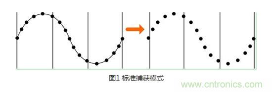
better observe the waveform is essentially to focus on measuring and analyzing the points of interest. How to capture the waveform with high fidelity starts with the process of the oscilloscope processing the signal. After the signal is processed by the front-end circuit of the oscilloscope, it comes to the ADC for analog-to-digital conversion. Next, the signal needs to be reconstructed and restored. This is the focus of this article, the capture mode of the oscilloscope. There are generally four capture modes, and different capture modes are suitable for observing different signals. Next, I will give you a brief introduction to the way the oscilloscope handles sampling points, that is, the capture mode of the oscilloscope. Standard capture mode The first thing to introduce is the standard capture mode. In this mode, the oscilloscope will sample the collected signal at equal intervals. The standard capture working mode also guarantees the original state of the signal to the greatest extent. For most waveforms, this mode can produce the best display effect. The following is the default capture mode of the ZDS2000 series oscilloscope. Peak capture mode Next is the peak capture mode. Just look at the name to know what it means. It is to collect the maximum and minimum values in a sampling interval signal. In this mode, occasional narrow pulse widths can be effectively observed. It is very practical in capturing high-frequency glitches. It can obtain the envelope of the signal or narrow pulses that may be lost. Using the peak capture mode will make the noise displayed by the waveform more obvious. Average capture mode
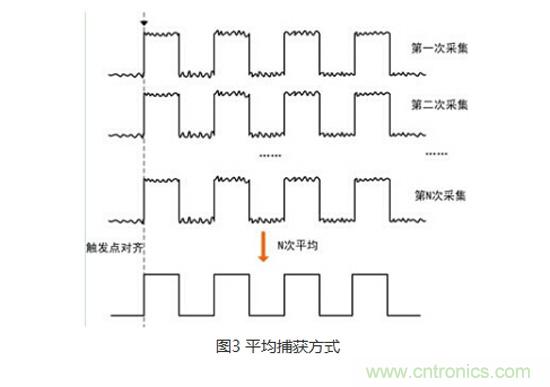
  The third one is the average capture mode. The name is also very easy to understand. It is to collect N screen signals, align them at the trigger position, and then perform an average operation. Using the average capture mode, while reducing noise, it maintains the original bandwidth. Filtering out noise is conducive to measuring the signal. It is suitable for observing periodic repetitive signals. Its filtering effect improves the vertical resolution of the oscilloscope. It is worth mentioning that average capture is particularly suitable for performing harmonic analysis or power quality analysis.
  High-resolution capture mode Finally, there is the high-resolution capture mode. For example, its working principle is to divide a waveform into 5 parts, and then average each point of one waveform, and finally one waveform becomes 5 points. This processing method can effectively improve the equivalent resolution of the system, which is essentially a digital filter. The more sampling points used for averaging, the more the resolution is improved, and the displayed waveform is smoother, thereby achieving the purpose of reducing noise. It should be noted that high resolution is to average the adjacent points of a waveform, so this mode is to sacrifice bandwidth for non-repeating signals to improve the test accuracy, so it is not suitable for testing high-frequency signals, and is suitable for observing high-resolution and low-bandwidth waveforms.
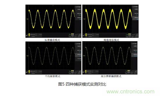
  Comparison of the four capture modes After understanding the working principles of the four capture modes, let's make a comparison. When inputting the same signal, noise can be observed in the standard capture mode, the noise of the signal is more obvious in the peak capture mode, and almost no random noise is seen in the average capture mode and high-resolution capture mode. According to the type of the measured signal and the test point that needs to be paid attention to, setting the corresponding capture mode can help us better observe the waveform and find and solve problems faster.
Reference address:Better waveform observation, revealing the four capture methods of oscilloscope
better observe the waveform is essentially to focus on measuring and analyzing the points of interest. How to capture the waveform with high fidelity starts with the process of the oscilloscope processing the signal. After the signal is processed by the front-end circuit of the oscilloscope, it comes to the ADC for analog-to-digital conversion. Next, the signal needs to be reconstructed and restored. This is the focus of this article, the capture mode of the oscilloscope. There are generally four capture modes, and different capture modes are suitable for observing different signals. Next, I will give you a brief introduction to the way the oscilloscope handles sampling points, that is, the capture mode of the oscilloscope. Standard capture mode The first thing to introduce is the standard capture mode. In this mode, the oscilloscope will sample the collected signal at equal intervals. The standard capture working mode also guarantees the original state of the signal to the greatest extent. For most waveforms, this mode can produce the best display effect. The following is the default capture mode of the ZDS2000 series oscilloscope.
 Peak capture mode Next is the peak capture mode. Just look at the name to know what it means. It is to collect the maximum and minimum values in a sampling interval signal. In this mode, occasional narrow pulse widths can be effectively observed. It is very practical in capturing high-frequency glitches. It can obtain the envelope of the signal or narrow pulses that may be lost. Using the peak capture mode will make the noise displayed by the waveform more obvious. Average capture mode
  The third one is the average capture mode. The name is also very easy to understand. It is to collect N screen signals, align them at the trigger position, and then perform an average operation. Using the average capture mode, while reducing noise, it maintains the original bandwidth. Filtering out noise is conducive to measuring the signal. It is suitable for observing periodic repetitive signals. Its filtering effect improves the vertical resolution of the oscilloscope. It is worth mentioning that average capture is particularly suitable for performing harmonic analysis or power quality analysis.
  High-resolution capture mode Finally, there is the high-resolution capture mode. For example, its working principle is to divide a waveform into 5 parts, and then average each point of one waveform, and finally one waveform becomes 5 points. This processing method can effectively improve the equivalent resolution of the system, which is essentially a digital filter. The more sampling points used for averaging, the more the resolution is improved, and the displayed waveform is smoother, thereby achieving the purpose of reducing noise. It should be noted that high resolution is to average the adjacent points of a waveform, so this mode is to sacrifice bandwidth for non-repeating signals to improve the test accuracy, so it is not suitable for testing high-frequency signals, and is suitable for observing high-resolution and low-bandwidth waveforms.
  Comparison of the four capture modes After understanding the working principles of the four capture modes, let's make a comparison. When inputting the same signal, noise can be observed in the standard capture mode, the noise of the signal is more obvious in the peak capture mode, and almost no random noise is seen in the average capture mode and high-resolution capture mode. According to the type of the measured signal and the test point that needs to be paid attention to, setting the corresponding capture mode can help us better observe the waveform and find and solve problems faster.
Previous article:If the oscilloscope is not isolated, will the signals between channels interfere with each other?
Next article:How to Correctly Measure Power Supply Ripple with an Oscilloscope
Recommended Content
Latest Test Measurement Articles
- Keysight Technologies Helps Samsung Electronics Successfully Validate FiRa® 2.0 Safe Distance Measurement Test Case
- From probes to power supplies, Tektronix is leading the way in comprehensive innovation in power electronics testing
- Seizing the Opportunities in the Chinese Application Market: NI's Challenges and Answers
- Tektronix Launches Breakthrough Power Measurement Tools to Accelerate Innovation as Global Electrification Accelerates
- Not all oscilloscopes are created equal: Why ADCs and low noise floor matter
- Enable TekHSI high-speed interface function to accelerate the remote transmission of waveform data
- How to measure the quality of soft start thyristor
- How to use a multimeter to judge whether a soft starter is good or bad
- What are the advantages and disadvantages of non-contact temperature sensors?
MoreSelected Circuit Diagrams
MorePopular Articles
- Innolux's intelligent steer-by-wire solution makes cars smarter and safer
- 8051 MCU - Parity Check
- How to efficiently balance the sensitivity of tactile sensing interfaces
- What should I do if the servo motor shakes? What causes the servo motor to shake quickly?
- 【Brushless Motor】Analysis of three-phase BLDC motor and sharing of two popular development boards
- Midea Industrial Technology's subsidiaries Clou Electronics and Hekang New Energy jointly appeared at the Munich Battery Energy Storage Exhibition and Solar Energy Exhibition
- Guoxin Sichen | Application of ferroelectric memory PB85RS2MC in power battery management, with a capacity of 2M
- Analysis of common faults of frequency converter
- In a head-on competition with Qualcomm, what kind of cockpit products has Intel come up with?
- Dalian Rongke's all-vanadium liquid flow battery energy storage equipment industrialization project has entered the sprint stage before production
MoreDaily News
- Allegro MicroSystems Introduces Advanced Magnetic and Inductive Position Sensing Solutions at Electronica 2024
- Car key in the left hand, liveness detection radar in the right hand, UWB is imperative for cars!
- After a decade of rapid development, domestic CIS has entered the market
- Aegis Dagger Battery + Thor EM-i Super Hybrid, Geely New Energy has thrown out two "king bombs"
- A brief discussion on functional safety - fault, error, and failure
- In the smart car 2.0 cycle, these core industry chains are facing major opportunities!
- The United States and Japan are developing new batteries. CATL faces challenges? How should China's new energy battery industry respond?
- Murata launches high-precision 6-axis inertial sensor for automobiles
- Ford patents pre-charge alarm to help save costs and respond to emergencies
- New real-time microcontroller system from Texas Instruments enables smarter processing in automotive and industrial applications
Guess you like
- Useful tutorial | How to quickly splice PCB data at unconventional angles?
- Class AB Audio Amplifier
- Max30102 heart rate blood oxygen sensor measures heart rate problem 2
- Xunwei IMX6 development board non-device tree source code compilation environment construction (I)
- Execution process before keil main
- I need help from a great God to look at this circuit diagram, thank you very much
- FPGA Global Clock Constraints (Xilinx)
- The 2020-2021 ON Semiconductor and Avnet IoT Innovation Design Competition awards have been announced!
- How to measure BLE power consumption (one of the most viewed app reports)
- Can anyone help explain the authentication process when the NB-IOT card is connected to the telecom network?

 Multisim Circuit System Design and Simulation Tutorial
 Hardware Design and PADS Design


 京公网安备 11010802033920号