Any production line requires minimizing costs and maximizing efficiency. To achieve this goal, Maxim has developed embedded flash programming application software for the MAX1441 proximity detection and touch sensor for automotive applications. The software continuously polls the JTAG interface through the USB port, trying to communicate with the MAX1441. Once the MAX1441 device is detected, the host will perform operations such as flash erase, write the specified firmware to the flash, and verify the written content, completing the above three operations in about 3 seconds. Before running the software, the device driver of the MAXQUSBJTAG-KIT must be correctly installed.
The MAX1441 programming software verifies that all necessary operations have been completed before proceeding to the next step to ensure that the operation has been completed. In addition, no user interaction such as keyboard or mouse operation is required during programming. The user only needs to plug in the MAX1441 and unplug it when the software automatically detects the presence of the MAX1441 after programming is completed. To avoid plugging and unplugging the MAX1441 while it is powered on, it may be necessary to control the power on/off. Multiple applications can be run on the same computer for flash programming. Each example requires a USB port and a MAXQUSBJTAG-KIT. When running multiple applications at the same time, there is no need to confirm which communication port (COM) the operating system has assigned to a specific device. When running multiple applications, it is best to connect the hardware to the USB port one by one and perform programming of one device before starting programming of the next device.
Require
The MAX1441 programming software requires the following equipment:
a. Windows XP?/Windows Vista?/7 (32-bit or 64-bit) computer.
b. Each application requires a corresponding USB port.
c. Each program requires a MAXIMUSB-JTAG interface board (MAXQUSBJTAG-KIT).
d.MAX1441VBAT power supply.
e. Firmware file with HEX extension, located in the same directory as the application.
f.MAX1441 test socket.
Software Installation
Download and unzip MAX1441_programmer.zip in a temporary folder, then follow the instructions to run Install_MAX1441_Programmer.exe. During the installation, the MAX1441_programmer application and supporting files will be downloaded and stored in the specified folder. The default directory is C:MAX1441. After the installation is complete, the contents of the folder will look similar to Figure 1.
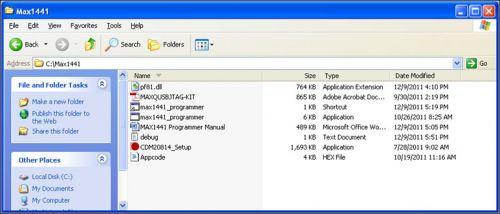
Figure 1.c: MAX1441 folder contents
Installing the Driver
Double-click the CDM20814_Setup file to install the FTDI Virtual COM Port driver, and your computer will display a screen similar to Figure 2. The driver installation will open a window and automatically close when complete.
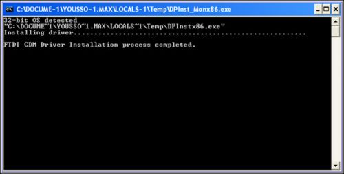
Figure 2. Installing the virtual comm port driver
USB-JTAG Adapter
After installing the FTDI virtual comm port driver, connect the MAXQUSBJTAG-KIT (Figure 3) to a USB port using the mini-USB connector.
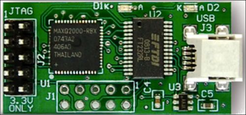
Figure 3. Maxim's USB-JTAG adapter (MAXQUSBJTAG-KIT)
Once the operating system finds a new hardware (adapter), it will load the previously installed driver. To verify, open DeviceManager and check the Ports (COM & LPT) device port, as shown in Figure 4.
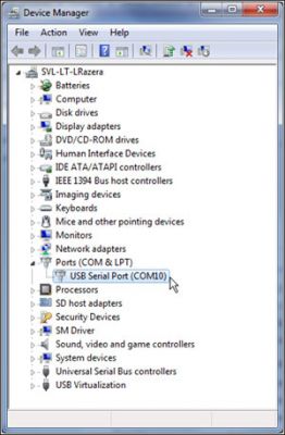
Figure 4. Maxim's USB-to-JTAG converter is identified as a USB serial port.
For detailed information about the MaximUSB-JTAG adapter, including details about driver installation, electrical characteristics, and functionality, refer to the MAXQUSBJTAG-KITPDF file, also located in the installation directory.
Programming steps
There are two ways to start the MAX1441 programming: directly or through a shortcut key. It is best to start the application through a shortcut key.
Direct start programming
To directly start the MAX1441 programming, double-click the MAX1441_Programmer application file. In the detailed file view, the program folder will look similar to Figure 5.
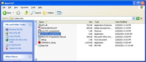
Figure 5.C: MAX1441 folder list, direct launch.
After starting the programmer, it will scan for available COM ports and search for the MaximUSB-JTAG interface board. Once a USB-JTAG interface is identified, the following screen (Figure 6) will appear, listing all HEX files (firmware) in the folder where the program is running. It should be noted that the identified COM port number is listed in the window title position. [page]
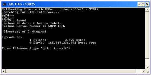
Figure 6. Screen display when directly starting the MAX1441 programmer.
The full file name (including the file extension) of the used firmware will appear in the program session.
Note:
Do not use spaces in file names; underscores "_" may be used instead.
Use firmware file names that are as short as possible.
Shortcut to start the programmer
To start the programmer from a shortcut, you first need to create a shortcut to the MAX1441 application and specify the firmware file name in the shortcut's properties window.
When using the shortcut key to launch the application, there is no need to enter the firmware file name, because the shortcut key contains the file name information to avoid operation errors, which is very suitable for production environments. To verify and/or modify the shortcut information, right-click on the shortcut key and select Properties (Figure 7). The default target of Properties|Shortcut is C:Max1441max1441_programmer.exeappcode.hex, where "appcode.hex" is the firmware name written to the MAX1441 device. For ease of use, copy the shortcut key to the PC desktop and run the program from the desktop.
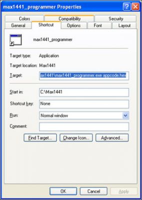
Figure 7. "MAX1441_Programmer" shortcut properties window
Once you start the MAX1441 Programmer, the screen's title bar will show the firmware file name and COM port number (Figure 8).
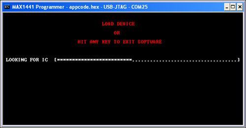
Figure 8. MAX1441 programmer search mode.
From this, the software starts searching for MAX1441, and the progress bar is completed in about 13 seconds. If MAX1441 is not found, it will return to the initial position. If any key on the keyboard is pressed, the program will be terminated.
Once the MAX1441 is found, programming of the flash memory begins and the window shown in Figure 9 is displayed.
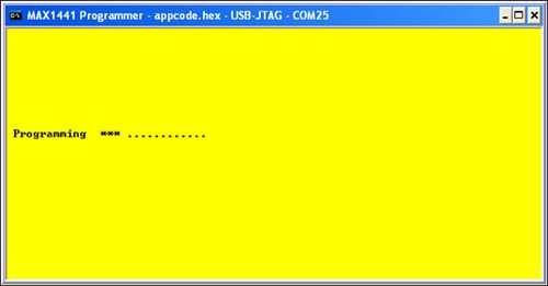
Figure 9. Programming mode of the MAX1441 programmer.
Note: Make sure that the programming process does not interfere with the MAX1441 interface (yellow window is displayed at the same time). Once the communication between the programmer and MAX1441 is interrupted, the programming will fail.
Figure 9 shows the progress of the program, with the “*” symbol indicating memory erase and flash write progress displayed during the process. Each cycle represents programming of 32 words of memory (64 bytes in total). The total number of cycles displayed depends on the size of the application firmware. When a programming session is complete, a green or red window will be displayed. If the device was successfully programmed, a green window will pop up (Figure 10). The programmer will immediately begin retrieving the next device for programming. If the installation process was not interrupted and the same device was retained during the installation, it will be reprogrammed after approximately 10 seconds. Pressing the ESC key will terminate programming and immediately initiate reprogramming of the same device. If the device is removed from the installation, a window will pop up (Figure 8) and programming will immediately begin once communication is established with the reloaded MAX1441.
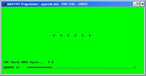
Figure 10. Status display of the MAX1441 programmer when it passes
If the MAX1441 fails to program, a red window will pop up (Figure 11). Remove the device and load another one, press any key (except ESC) to restart programming, or press ESC to terminate the application.
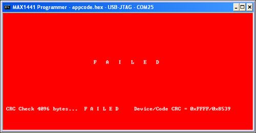
Figure 11. Status display when the MAX1441 programmer fails to run
In addition to popping up green and red windows to indicate the success/failure of the program, the application can also trigger the OUT1 and OUT2 pins of the MAX1441 to reflect the program's progress and results:
After the flash erase operation is complete, the OUT1 and OUT2 pins are pulled low and then released. On the MAX1441 EV kit, this causes LED1 and LED2 to blink.
If the flash memory is programmed successfully, the OUT1 pin will be pulled low. On the MAX1441 EV kit, this will light up LED1. OUT1 will remain low until the MAX1441 is removed or the next programming cycle is started.
If flash programming is unsuccessful, OUT2 will be pulled low. On the MAX1441 EV kit, this will light LED2. OUT2 will remain low until the MAX1441 is removed or the next programming cycle is started.
After completing programming of the current MAX1441, remove the device from the socket and insert the next device to be programmed.
In an automated production environment, this application can be used to screen good and bad devices based on the status of the OUT1 and OUT2 pins.
Note: Do not disconnect the USB cable while programming the MAX1441, which is connected to the computer via Maxim's USB-JTAG interface board. Any interruption will cause the application to fail.
Previous article:Remote sensing technology application
Next article:How to choose a mass flow meter for measurement?
- Keysight Technologies Helps Samsung Electronics Successfully Validate FiRa® 2.0 Safe Distance Measurement Test Case
- From probes to power supplies, Tektronix is leading the way in comprehensive innovation in power electronics testing
- Seizing the Opportunities in the Chinese Application Market: NI's Challenges and Answers
- Tektronix Launches Breakthrough Power Measurement Tools to Accelerate Innovation as Global Electrification Accelerates
- Not all oscilloscopes are created equal: Why ADCs and low noise floor matter
- Enable TekHSI high-speed interface function to accelerate the remote transmission of waveform data
- How to measure the quality of soft start thyristor
- How to use a multimeter to judge whether a soft starter is good or bad
- What are the advantages and disadvantages of non-contact temperature sensors?
- Innolux's intelligent steer-by-wire solution makes cars smarter and safer
- 8051 MCU - Parity Check
- How to efficiently balance the sensitivity of tactile sensing interfaces
- What should I do if the servo motor shakes? What causes the servo motor to shake quickly?
- 【Brushless Motor】Analysis of three-phase BLDC motor and sharing of two popular development boards
- Midea Industrial Technology's subsidiaries Clou Electronics and Hekang New Energy jointly appeared at the Munich Battery Energy Storage Exhibition and Solar Energy Exhibition
- Guoxin Sichen | Application of ferroelectric memory PB85RS2MC in power battery management, with a capacity of 2M
- Analysis of common faults of frequency converter
- In a head-on competition with Qualcomm, what kind of cockpit products has Intel come up with?
- Dalian Rongke's all-vanadium liquid flow battery energy storage equipment industrialization project has entered the sprint stage before production
- Allegro MicroSystems Introduces Advanced Magnetic and Inductive Position Sensing Solutions at Electronica 2024
- Car key in the left hand, liveness detection radar in the right hand, UWB is imperative for cars!
- After a decade of rapid development, domestic CIS has entered the market
- Aegis Dagger Battery + Thor EM-i Super Hybrid, Geely New Energy has thrown out two "king bombs"
- A brief discussion on functional safety - fault, error, and failure
- In the smart car 2.0 cycle, these core industry chains are facing major opportunities!
- The United States and Japan are developing new batteries. CATL faces challenges? How should China's new energy battery industry respond?
- Murata launches high-precision 6-axis inertial sensor for automobiles
- Ford patents pre-charge alarm to help save costs and respond to emergencies
- New real-time microcontroller system from Texas Instruments enables smarter processing in automotive and industrial applications
- Essential for EMC Electronic Engineers
- Can you help me take a look at this FPGA development board?
- FLUKE is hiring!
- How do you access Google Search?
- Help, about converting hexadecimal to numeric value (LIS25BA)
- FPGA realizes digital tube counting
- MSP430FW42X Non-Magnetic Sensor Water Meter Solution
- Error handling in C programming for embedded systems
- RF calculation formula backup one
- How to Redefine the Size of Information Memory and Persistent Memory in FRAM

 Introduction to Artificial Intelligence and Robotics (Murphy)
 Multithreading in LabVIEW


 京公网安备 11010802033920号