Resistivity is measured by measuring the resistance and then converting it to surface or volume resistivity to account for geometry. The ideal method for measuring the resistance of insulating materials is to apply a known voltage to the sample and measure the resulting current using an electrometer or picoammeter. To account for sample geometry, conveniently sized electrodes should be used, such as the Keithley Model 8009 Resistivity Tester. Its electrodes meet the requirements of ASTM Standard D257, "DC Resistance or Conductance of Insulating Materials." This article details how to use these test fixtures to make surface and volume resistivity measurements, as well as the techniques of changing polarity and changing voltage when measuring resistivity.
Measurement of Volume Resistivity
Volume resistivity is a measure of a material's ability to pass leakage current directly. Volume resistivity is defined as the resistance of a cube of insulating material with a side length of 1 cm and is expressed in ohm-cm. To measure volume resistivity, the sample is placed between two electrodes and a potential difference is applied between the two electrodes. The resulting current will be distributed in the body of the test sample and measured by the picoammeter or electrometer. Resistivity is calculated from the geometry of the electrodes and the thickness of the sample:

Where:ρ = Bulk resistivity (ohm-cm)
KV = Bulk resistivity cell constant determined by the geometry of the test cell (cm2)
V = Applied voltage (volts)
I = Measured current (amperes)
t = Thickness of the sample (cm)
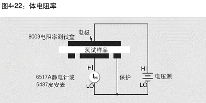
Figure 4-22 shows a configuration for measuring bulk resistivity in accordance with ASTM D257. In this circuit, the HI terminal of the ammeter is connected to the bottom electrode and the HI terminal of the voltage source is connected to the top electrode. The LO terminal of the ammeter and the LO terminal of the voltage source are connected together. The outer electrode at the bottom is connected to the guard terminal (LO terminal of the ammeter) to avoid including surface leakage current in the measurement.

Measuring Surface ResistivitySurface
resistivity is defined as the resistance of the surface of a material and is expressed in ohms (often called sheet resistance). It is measured by placing two electrodes on the surface of the test sample, applying a potential difference between the electrodes, and measuring the resulting current. Surface resistivity is calculated as follows:

Where:σ = Surface resistivity (ohms)
KS = Surface resistivity cell constant determined by the geometry of the test cellV
= Applied voltage (volts)
I = Measured current (amperes)
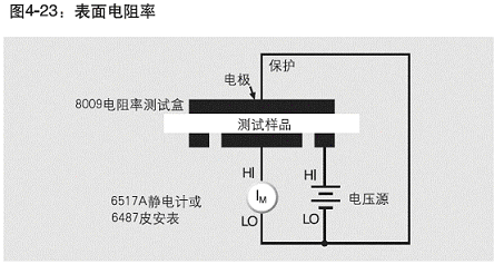
Figure 4-23 shows the configuration for measuring surface resistivity. This configuration is similar to the circuit for making bulk resistivity measurements, except now the resistance is measured between the two electrodes at the bottom. Note that the top electrode is shielded so that only the current flowing through the surface of the insulator is measured by the picoammeter.Test

ParametersBulk
and surface resistivity measurements are determined by several factors. First, they are a function of the applied voltage. Sometimes the voltage is intentionally varied to determine the dependence of the insulator's resistivity on voltage. Resistivity also varies with the length of the charging time. Since the material charges exponentially, the longer the voltage is applied, the lower the measured current becomes. [page]
Humidity has a significant effect on surface resistivity measurements, and to a lesser extent on bulk resistivity measurements. Humidity will cause surface resistivity measurements to be lower than normal.
In order to make accurate comparisons between specific test runs, the applied voltage, charging time, and environmental conditions should be kept constant from one test to another.
Using the Keithley Model 8009 Resistivity Tester
No sample preparation is required when using the Model 8009 Resistivity Tester. This test fixture provides a standardized electrode configuration that eliminates the need to spray electrodes on the sample or use mercury-filled rings. The recommended sample size when using this test fixture is 2.5 to 4 inches in diameter and up to 0.125 inches thick.
Certain particularly hard samples, such as glass, epoxy, and ceramics require an interface between the stainless steel electrode and the sample surface. The Model 8009 is equipped with conductive rubber on the top and bottom electrodes to enhance the surface contact between the sample and the test fixture. Since the area of the electrode becomes the area of contact with the medium, special attention must be paid. If the configuration and size of the electrodes are different, the conversion constants provided by the system may not be valid. The
Model 8009 uses a safety interlock mechanism that prevents high voltage from being applied to the electrodes until the lid of the test fixture is closed. This device also shields the sample from electrostatic interference.
Bias Correction Techniques
When measuring very high resistivity materials, background currents may cause measurement errors. Background currents may be caused by stored charge in the material (dielectric absorption), electrostatic or triboelectric charges, or piezoelectric effects. Background currents may be equal to or greater than the current excited by the applied voltage source. If the background current is of the same polarity as the current being measured, the measured current value will be much greater than the true value. If the background current is of reverse polarity, this undesirable current may cause a reverse polarity current reading. That is, the polarity of the current is opposite to the polarity of the applied voltage, and the calculated resistance will be negative. To correct this problem, a polarity-reversal and voltage-reversal method can be used to virtually eliminate the effect of background current on the sample.
Reversal Polarity Method
The Reversal Polarity Method applies a positive bias voltage and then measures the current after a specified delay time. The polarity is then reversed and the current is measured again after the same delay time. This polarity reversal process can be repeated any number of times. The resistance value is calculated as a weighted average of the most recent current measurements. The
Model 6517A Electrometer and the Reversal Polarity Method are built into a ready-made test program. Using this method, the user enters the test voltage, measurement time, and number of repetitions. The instrument calculates the final resistance value and stores it in memory.
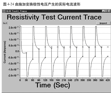
The Model 6524 High Resistance Test software allows the user to observe the actual current waveform produced by applying a test voltage of alternating polarity. A typical waveform is shown in Figure 4-24. Note the exponential decay of the current when using positive and negative test voltages. The X marked in the figure represents the current calculated as a weighted average of the last few measurements.

In addition to the high resistance test, the software includes three other programs. The HI-R Step Response Program analyzes the current transients produced by applying a voltage stimulus and can be used to determine the appropriate measurement time for a given sample. The HI-RSweep Test program measures current or resistance while sweeping one of the following parameters. The parameters that can be swept are: voltage of alternating polarity, bias voltage, or measurement time. The HI-R, T and RH program plots resistance versus time and, with the appropriate probes, resistance versus temperature or relative humidity.
The Model
6487 Picoammeter Voltage Source has a built-in alternating voltage polarity ohms mode. This mode makes two current measurements, one at the user specified test voltage and one at 0 V. This mode eliminates the effects of background current by determining the difference between the two currents produced by each voltage.
Reference address:Measurement of surface resistivity and volume resistivity as well as polarity and voltage conversion
Measurement of Volume Resistivity
Volume resistivity is a measure of a material's ability to pass leakage current directly. Volume resistivity is defined as the resistance of a cube of insulating material with a side length of 1 cm and is expressed in ohm-cm. To measure volume resistivity, the sample is placed between two electrodes and a potential difference is applied between the two electrodes. The resulting current will be distributed in the body of the test sample and measured by the picoammeter or electrometer. Resistivity is calculated from the geometry of the electrodes and the thickness of the sample:

Where:ρ = Bulk resistivity (ohm-cm)
KV = Bulk resistivity cell constant determined by the geometry of the test cell (cm2)
V = Applied voltage (volts)
I = Measured current (amperes)
t = Thickness of the sample (cm)
Figure 4-22 shows a configuration for measuring bulk resistivity in accordance with ASTM D257. In this circuit, the HI terminal of the ammeter is connected to the bottom electrode and the HI terminal of the voltage source is connected to the top electrode. The LO terminal of the ammeter and the LO terminal of the voltage source are connected together. The outer electrode at the bottom is connected to the guard terminal (LO terminal of the ammeter) to avoid including surface leakage current in the measurement.

Measuring Surface ResistivitySurface
resistivity is defined as the resistance of the surface of a material and is expressed in ohms (often called sheet resistance). It is measured by placing two electrodes on the surface of the test sample, applying a potential difference between the electrodes, and measuring the resulting current. Surface resistivity is calculated as follows:

Where:σ = Surface resistivity (ohms)
KS = Surface resistivity cell constant determined by the geometry of the test cellV
= Applied voltage (volts)
I = Measured current (amperes)
Figure 4-23 shows the configuration for measuring surface resistivity. This configuration is similar to the circuit for making bulk resistivity measurements, except now the resistance is measured between the two electrodes at the bottom. Note that the top electrode is shielded so that only the current flowing through the surface of the insulator is measured by the picoammeter.Test

ParametersBulk
and surface resistivity measurements are determined by several factors. First, they are a function of the applied voltage. Sometimes the voltage is intentionally varied to determine the dependence of the insulator's resistivity on voltage. Resistivity also varies with the length of the charging time. Since the material charges exponentially, the longer the voltage is applied, the lower the measured current becomes. [page]
Humidity has a significant effect on surface resistivity measurements, and to a lesser extent on bulk resistivity measurements. Humidity will cause surface resistivity measurements to be lower than normal.
In order to make accurate comparisons between specific test runs, the applied voltage, charging time, and environmental conditions should be kept constant from one test to another.
Using the Keithley Model 8009 Resistivity Tester
No sample preparation is required when using the Model 8009 Resistivity Tester. This test fixture provides a standardized electrode configuration that eliminates the need to spray electrodes on the sample or use mercury-filled rings. The recommended sample size when using this test fixture is 2.5 to 4 inches in diameter and up to 0.125 inches thick.
Certain particularly hard samples, such as glass, epoxy, and ceramics require an interface between the stainless steel electrode and the sample surface. The Model 8009 is equipped with conductive rubber on the top and bottom electrodes to enhance the surface contact between the sample and the test fixture. Since the area of the electrode becomes the area of contact with the medium, special attention must be paid. If the configuration and size of the electrodes are different, the conversion constants provided by the system may not be valid. The
Model 8009 uses a safety interlock mechanism that prevents high voltage from being applied to the electrodes until the lid of the test fixture is closed. This device also shields the sample from electrostatic interference.
Bias Correction Techniques
When measuring very high resistivity materials, background currents may cause measurement errors. Background currents may be caused by stored charge in the material (dielectric absorption), electrostatic or triboelectric charges, or piezoelectric effects. Background currents may be equal to or greater than the current excited by the applied voltage source. If the background current is of the same polarity as the current being measured, the measured current value will be much greater than the true value. If the background current is of reverse polarity, this undesirable current may cause a reverse polarity current reading. That is, the polarity of the current is opposite to the polarity of the applied voltage, and the calculated resistance will be negative. To correct this problem, a polarity-reversal and voltage-reversal method can be used to virtually eliminate the effect of background current on the sample.
Reversal Polarity Method
The Reversal Polarity Method applies a positive bias voltage and then measures the current after a specified delay time. The polarity is then reversed and the current is measured again after the same delay time. This polarity reversal process can be repeated any number of times. The resistance value is calculated as a weighted average of the most recent current measurements. The
Model 6517A Electrometer and the Reversal Polarity Method are built into a ready-made test program. Using this method, the user enters the test voltage, measurement time, and number of repetitions. The instrument calculates the final resistance value and stores it in memory.
The Model 6524 High Resistance Test software allows the user to observe the actual current waveform produced by applying a test voltage of alternating polarity. A typical waveform is shown in Figure 4-24. Note the exponential decay of the current when using positive and negative test voltages. The X marked in the figure represents the current calculated as a weighted average of the last few measurements.

In addition to the high resistance test, the software includes three other programs. The HI-R Step Response Program analyzes the current transients produced by applying a voltage stimulus and can be used to determine the appropriate measurement time for a given sample. The HI-RSweep Test program measures current or resistance while sweeping one of the following parameters. The parameters that can be swept are: voltage of alternating polarity, bias voltage, or measurement time. The HI-R, T and RH program plots resistance versus time and, with the appropriate probes, resistance versus temperature or relative humidity.
The Model
6487 Picoammeter Voltage Source has a built-in alternating voltage polarity ohms mode. This mode makes two current measurements, one at the user specified test voltage and one at 0 V. This mode eliminates the effects of background current by determining the difference between the two currents produced by each voltage.
Previous article:Three Classical Methods for Measuring the Resistivity of Conductive Materials
Next article:Approach to Implementing and Testing Switching Hardware
- Popular Resources
- Popular amplifiers
Recommended Content
Latest Test Measurement Articles
- From probes to power supplies, Tektronix is leading the way in comprehensive innovation in power electronics testing
- Seizing the Opportunities in the Chinese Application Market: NI's Challenges and Answers
- Tektronix Launches Breakthrough Power Measurement Tools to Accelerate Innovation as Global Electrification Accelerates
- Not all oscilloscopes are created equal: Why ADCs and low noise floor matter
- Enable TekHSI high-speed interface function to accelerate the remote transmission of waveform data
- How to measure the quality of soft start thyristor
- How to use a multimeter to judge whether a soft starter is good or bad
- What are the advantages and disadvantages of non-contact temperature sensors?
- In what situations are non-contact temperature sensors widely used?
MoreSelected Circuit Diagrams
MorePopular Articles
- LED chemical incompatibility test to see which chemicals LEDs can be used with
- Application of ARM9 hardware coprocessor on WinCE embedded motherboard
- What are the key points for selecting rotor flowmeter?
- LM317 high power charger circuit
- A brief analysis of Embest's application and development of embedded medical devices
- Single-phase RC protection circuit
- stm32 PVD programmable voltage monitor
- Introduction and measurement of edge trigger and level trigger of 51 single chip microcomputer
- Improved design of Linux system software shell protection technology
- What to do if the ABB robot protection device stops
MoreDaily News
- Innovation is not limited to Meizhi, Welling will appear at the 2024 China Home Appliance Technology Conference
- Huawei's Strategic Department Director Gai Gang: The cumulative installed base of open source Euler operating system exceeds 10 million sets
- Download from the Internet--ARM Getting Started Notes
- Learn ARM development(22)
- Learn ARM development(21)
- Learn ARM development(20)
- Learn ARM development(19)
- Learn ARM development(14)
- Learn ARM development(15)
- Analysis of the application of several common contact parts in high-voltage connectors of new energy vehicles
Guess you like
- [HC32F460 Development Board Review] 02 Build a development environment to implement the LED marquee function
- Qorvo follows the animation to grasp the 5G RF front-end trend
- Microwave Technology and Antennas (4th Edition)
- [AutoChips AC7801x motor demo board review] + unboxing and GPIO lighting
- About the master: zhang2018yi
- Qorvo has a few things to tell you about WiFi 6
- What kind of switch is this? Where can I buy one?
- Chapter 3: Use of GPIO
- Software Installation
- If you don’t lose weight in spring, you will regret it in summer. Let me share some tips on how to lose weight and keep in shape!

 MAX4461HETT+T


 京公网安备 11010802033920号