For a battery-powered system, the efficiency of the entire system is an important design parameter. It affects both the battery capacity required and the operating time of the end product. The correct efficiency and operating time of the system can only be obtained when the power efficiency is accurately measured. Most battery-powered systems use the power characteristic of pulse frequency modulation (PFM) to improve the power efficiency at low loads. The same characteristic that helps PFM achieve high efficiency makes it challenging to accurately measure efficiency. When measuring
the efficiency of a DC/DC converter in PFM mode, special care must be taken to ensure accurate measurements. Since the converter operates in PFM mode, the measurement settings of the converter are different from the actual PWM operating mode. In fact, an unreasonable measurement setting may result in erroneous efficiency measurement data, which may be significantly different from the specifications given in the data sheet. This article discusses PFM mode and how it maintains high efficiency at low loads, and provides engineers with some guidance on how to achieve accurate efficiency measurements.
Pulse Frequency Modulation
Pulse frequency modulation is a switching method commonly used in DC/DC voltage converters to improve efficiency at low loads. This method is also often referred to as transient mode and power saving mode (PSM). PSM has a significant advantage over conventional PWM in that it reduces the power consumption of the converter at low loads.
A switching converter has two types of power consumption: static power and dynamic power. Static power is a constant value that is independent of the load current. Dynamic power, on the other hand, increases with load current. An example of static power is the quiescent current that enters the IC, which acts on internal circuits such as the bandgap reference, operational amplifier, and internal clock. Dynamic power can be divided into two types, conduction loss and switching loss. Conduction losses are load-dependent and include losses caused by the voltage drop across the power FETs and inductors of the power supply. High load currents result in high conduction losses. In addition, the converter has frequency-dependent switching losses, including switching losses of the FETs, gate drive losses, and power dissipation in the body diode during each switching cycle. As the name implies, these losses are proportional to the switching frequency. Most of these losses are also load-dependent. Figure 1 shows the dynamic and static power consumption of a low-power integrated circuit, with dynamic power dominating when the output current is high and static power dominating when the output current is low.
To reduce power consumption at low loads, many converters use an "Energy Saving" mode. This mode uses pulse frequency modulation at low load currents. This method uses a variety of power-saving schemes to maintain high efficiency at light loads. In contrast to PWM mode, which requires the converter to switch continuously, PFM mode allows the converter to switch for short periods of time. TI's TPS62350 chip can achieve the best efficiency over the full input voltage range by varying the load current in PFM mode. The minimum load current threshold for PFM is Vin/25Ω. When the converter uses PFM mode, it only switches when necessary to support the load and maintain the output voltage. When the output voltage falls below the set value, the IC triggers the switch, and the output voltage starts to rise after the IC turns on. This may take one or several switching cycles. Once the output voltage reaches the set range, the converter stops switching. At this time, the load current is provided by the output capacitor, and the output voltage drops. When the voltage falls below the set minimum, the converter starts to work again. In this way, the converter saves a lot of power when it is not working. Figure 2 shows this switching function. Figure
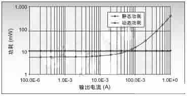
1: Comparison of dynamic and static power consumption of switching converters.
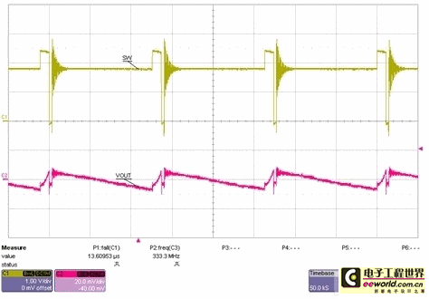
Figure 2: Switching points when operating in PFM mode.
When switching is stopped, it is obvious that the converter has significantly reduced quiescent current by shutting down all unnecessary internal circuitry. The only internal circuitry that remains active is the bandgap reference and a comparator that monitors the output voltage. Since the switch is in the off state, all switching power dissipation is reduced to zero. Most converters operate in discontinuous conduction mode (DCM) when in PFM mode. DCM mode prevents the inductor current from becoming negative, thereby avoiding unnecessary conduction losses in the inductor and power switch. These power savings are significant at low loads compared to standard PWM mode. Figure 3 shows the efficiency of both PFM and PWM modes. At an output current of 1mA, the efficiency of PFM mode is 55% higher than that of PWM mode. Figure 3
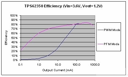
: Comparison of PFM and PWM mode efficiency for accurate measurement.
In battery-powered systems, the power saving advantages of PFM will play a significant role in extending the system's operating time. However, to correctly model the system's efficiency and operating time, accurate measurement of the power supply efficiency is required for both PWM and PFM modes. When measuring the efficiency of DC/DC converters, the correct connection of the voltage and current meter is very important for accurate measurement. [page]
Figure 4 shows the exact steps to take when measuring power in PWM mode, and the exact placement of the voltage and current meters for each measurement. Most lab power supplies display the output voltage, but be careful not to use this value in your efficiency calculations. Instead, measure it with a separate voltage meter connected directly to the input of the device under test (DUT). This ensures that you get the true input voltage to the DUT, while also eliminating voltage drops on the device power cord or the current meter. The current meter must be placed between the power supply and the DUT. Similarly, a separate voltage meter is required at the output of the DUT to correctly measure the output voltage. The output voltage should be measured at the regulation point of the power supply, not the voltage across the load. Note that Kelvin connections are used for both input and output voltage measurements. This allows measurement errors caused by connector IR drops to be ignored. Connecting the output current meter in series with the load as shown in Figure 4 allows current load measurements to be made.
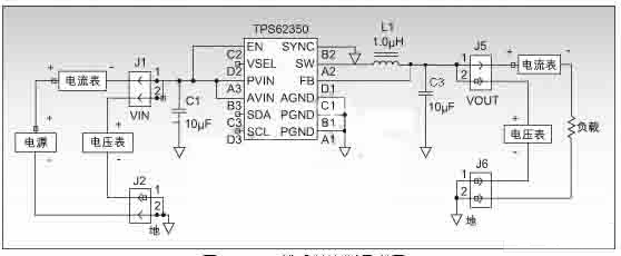
Figure 4: PWM mode efficiency measurement configuration.
PFM achieves high efficiency, but makes accurate efficiency measurements more difficult. In Figure 5, a triangle wave is used as the input current to the FPM mode converter. The converter only produces current when the switch is on. Most DMMs cannot accurately measure the average input current when the power supply is switching in PFM mode. Instead, they measure an effective value that is usually greater than the average value unless the current is pure DC. Engineers can only accurately measure the efficiency by measuring the average input current. This problem can be easily solved by adding a large capacitor to the DUT input, as shown in Figure 6. Now that the lab power supply is providing DC current to the DUT, the average current input to the DUT input will not change. The added capacitor filters out the AC component of the current required by the DUT and leaves the lab power supply to provide only the average DC current.
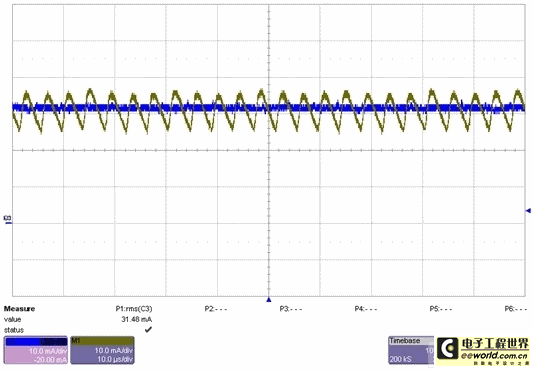
Figure 5: Input current waveform. The
DC waveform in Figure 5 is the input current that would be measured by adding a capacitor to the DUT input as shown in Figure 6. Accurately measuring the average input current requires the correct placement of the input current meter. Although pure DC is passing through the meter, the current waveform produced by the added capacitor is similar to the previous triangle wave without the DC bias. Therefore, the role of the capacitor can be seen as splitting the input current into two components, DC and AC. It is best to choose an additional capacitor with a capacity of 20 times the input capacitance of the power supply. Use an ammeter to measure the laboratory power supply current and observe the DC waveform with an oscilloscope. If there is still an AC component, increase the capacitor capacity. The capacitor used should have a low ESR (<100mohm).

Figure 6: PFM mode efficiency measurement configuration.
Using the setup method shown in Figure 4 to measure PFM efficiency may cause the measured data to deviate from the true value by up to 15%, especially when the input voltage is low and the load current is small. Figure 7 compares the efficiency measurement results of adding input capacitors and not adding capacitors. It turns out that adding capacitors is necessary, and its efficiency will be 5% higher than when no capacitors are added.
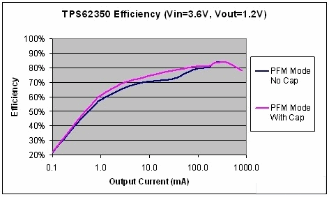
Figure 7: Comparison of using input capacitors and not using input capacitors in PFM mode.
Summary of this article
Light load efficiency is critical to extend battery life in portable applications. PFM mode uses several methods to improve efficiency at light loads, but incorrect efficiency measurements at this time will mask the gains. Measuring the efficiency of DC/DC voltage converters must be done with great care to achieve precise measurements. It is critical to carefully set up the sensing instrumentation, regardless of whether the converter is operating in PFM or PWM mode. In addition, a large capacitor can be added to the converter input to ensure accurate efficiency measurements when in PFM mode.
Reference address:A Practical Guide to Efficiency Measurements in Low-Power Designs
the efficiency of a DC/DC converter in PFM mode, special care must be taken to ensure accurate measurements. Since the converter operates in PFM mode, the measurement settings of the converter are different from the actual PWM operating mode. In fact, an unreasonable measurement setting may result in erroneous efficiency measurement data, which may be significantly different from the specifications given in the data sheet. This article discusses PFM mode and how it maintains high efficiency at low loads, and provides engineers with some guidance on how to achieve accurate efficiency measurements.
Pulse Frequency Modulation
Pulse frequency modulation is a switching method commonly used in DC/DC voltage converters to improve efficiency at low loads. This method is also often referred to as transient mode and power saving mode (PSM). PSM has a significant advantage over conventional PWM in that it reduces the power consumption of the converter at low loads.
A switching converter has two types of power consumption: static power and dynamic power. Static power is a constant value that is independent of the load current. Dynamic power, on the other hand, increases with load current. An example of static power is the quiescent current that enters the IC, which acts on internal circuits such as the bandgap reference, operational amplifier, and internal clock. Dynamic power can be divided into two types, conduction loss and switching loss. Conduction losses are load-dependent and include losses caused by the voltage drop across the power FETs and inductors of the power supply. High load currents result in high conduction losses. In addition, the converter has frequency-dependent switching losses, including switching losses of the FETs, gate drive losses, and power dissipation in the body diode during each switching cycle. As the name implies, these losses are proportional to the switching frequency. Most of these losses are also load-dependent. Figure 1 shows the dynamic and static power consumption of a low-power integrated circuit, with dynamic power dominating when the output current is high and static power dominating when the output current is low.
To reduce power consumption at low loads, many converters use an "Energy Saving" mode. This mode uses pulse frequency modulation at low load currents. This method uses a variety of power-saving schemes to maintain high efficiency at light loads. In contrast to PWM mode, which requires the converter to switch continuously, PFM mode allows the converter to switch for short periods of time. TI's TPS62350 chip can achieve the best efficiency over the full input voltage range by varying the load current in PFM mode. The minimum load current threshold for PFM is Vin/25Ω. When the converter uses PFM mode, it only switches when necessary to support the load and maintain the output voltage. When the output voltage falls below the set value, the IC triggers the switch, and the output voltage starts to rise after the IC turns on. This may take one or several switching cycles. Once the output voltage reaches the set range, the converter stops switching. At this time, the load current is provided by the output capacitor, and the output voltage drops. When the voltage falls below the set minimum, the converter starts to work again. In this way, the converter saves a lot of power when it is not working. Figure 2 shows this switching function. Figure

1: Comparison of dynamic and static power consumption of switching converters.

Figure 2: Switching points when operating in PFM mode.
When switching is stopped, it is obvious that the converter has significantly reduced quiescent current by shutting down all unnecessary internal circuitry. The only internal circuitry that remains active is the bandgap reference and a comparator that monitors the output voltage. Since the switch is in the off state, all switching power dissipation is reduced to zero. Most converters operate in discontinuous conduction mode (DCM) when in PFM mode. DCM mode prevents the inductor current from becoming negative, thereby avoiding unnecessary conduction losses in the inductor and power switch. These power savings are significant at low loads compared to standard PWM mode. Figure 3 shows the efficiency of both PFM and PWM modes. At an output current of 1mA, the efficiency of PFM mode is 55% higher than that of PWM mode. Figure 3

: Comparison of PFM and PWM mode efficiency for accurate measurement.
In battery-powered systems, the power saving advantages of PFM will play a significant role in extending the system's operating time. However, to correctly model the system's efficiency and operating time, accurate measurement of the power supply efficiency is required for both PWM and PFM modes. When measuring the efficiency of DC/DC converters, the correct connection of the voltage and current meter is very important for accurate measurement. [page]
Figure 4 shows the exact steps to take when measuring power in PWM mode, and the exact placement of the voltage and current meters for each measurement. Most lab power supplies display the output voltage, but be careful not to use this value in your efficiency calculations. Instead, measure it with a separate voltage meter connected directly to the input of the device under test (DUT). This ensures that you get the true input voltage to the DUT, while also eliminating voltage drops on the device power cord or the current meter. The current meter must be placed between the power supply and the DUT. Similarly, a separate voltage meter is required at the output of the DUT to correctly measure the output voltage. The output voltage should be measured at the regulation point of the power supply, not the voltage across the load. Note that Kelvin connections are used for both input and output voltage measurements. This allows measurement errors caused by connector IR drops to be ignored. Connecting the output current meter in series with the load as shown in Figure 4 allows current load measurements to be made.

Figure 4: PWM mode efficiency measurement configuration.
PFM achieves high efficiency, but makes accurate efficiency measurements more difficult. In Figure 5, a triangle wave is used as the input current to the FPM mode converter. The converter only produces current when the switch is on. Most DMMs cannot accurately measure the average input current when the power supply is switching in PFM mode. Instead, they measure an effective value that is usually greater than the average value unless the current is pure DC. Engineers can only accurately measure the efficiency by measuring the average input current. This problem can be easily solved by adding a large capacitor to the DUT input, as shown in Figure 6. Now that the lab power supply is providing DC current to the DUT, the average current input to the DUT input will not change. The added capacitor filters out the AC component of the current required by the DUT and leaves the lab power supply to provide only the average DC current.

Figure 5: Input current waveform. The
DC waveform in Figure 5 is the input current that would be measured by adding a capacitor to the DUT input as shown in Figure 6. Accurately measuring the average input current requires the correct placement of the input current meter. Although pure DC is passing through the meter, the current waveform produced by the added capacitor is similar to the previous triangle wave without the DC bias. Therefore, the role of the capacitor can be seen as splitting the input current into two components, DC and AC. It is best to choose an additional capacitor with a capacity of 20 times the input capacitance of the power supply. Use an ammeter to measure the laboratory power supply current and observe the DC waveform with an oscilloscope. If there is still an AC component, increase the capacitor capacity. The capacitor used should have a low ESR (<100mohm).

Figure 6: PFM mode efficiency measurement configuration.
Using the setup method shown in Figure 4 to measure PFM efficiency may cause the measured data to deviate from the true value by up to 15%, especially when the input voltage is low and the load current is small. Figure 7 compares the efficiency measurement results of adding input capacitors and not adding capacitors. It turns out that adding capacitors is necessary, and its efficiency will be 5% higher than when no capacitors are added.

Figure 7: Comparison of using input capacitors and not using input capacitors in PFM mode.
Summary of this article
Light load efficiency is critical to extend battery life in portable applications. PFM mode uses several methods to improve efficiency at light loads, but incorrect efficiency measurements at this time will mask the gains. Measuring the efficiency of DC/DC voltage converters must be done with great care to achieve precise measurements. It is critical to carefully set up the sensing instrumentation, regardless of whether the converter is operating in PFM or PWM mode. In addition, a large capacitor can be added to the converter input to ensure accurate efficiency measurements when in PFM mode.
Previous article:Design of a wind speed sensor based on platinum resistance
Next article:FBG Optical Sensor Basics
- Popular Resources
- Popular amplifiers
Recommended Content
Latest Test Measurement Articles
- Keysight Technologies Helps Samsung Electronics Successfully Validate FiRa® 2.0 Safe Distance Measurement Test Case
- From probes to power supplies, Tektronix is leading the way in comprehensive innovation in power electronics testing
- Seizing the Opportunities in the Chinese Application Market: NI's Challenges and Answers
- Tektronix Launches Breakthrough Power Measurement Tools to Accelerate Innovation as Global Electrification Accelerates
- Not all oscilloscopes are created equal: Why ADCs and low noise floor matter
- Enable TekHSI high-speed interface function to accelerate the remote transmission of waveform data
- How to measure the quality of soft start thyristor
- How to use a multimeter to judge whether a soft starter is good or bad
- What are the advantages and disadvantages of non-contact temperature sensors?
MoreSelected Circuit Diagrams
MorePopular Articles
- LED chemical incompatibility test to see which chemicals LEDs can be used with
- Application of ARM9 hardware coprocessor on WinCE embedded motherboard
- What are the key points for selecting rotor flowmeter?
- LM317 high power charger circuit
- A brief analysis of Embest's application and development of embedded medical devices
- Single-phase RC protection circuit
- stm32 PVD programmable voltage monitor
- Introduction and measurement of edge trigger and level trigger of 51 single chip microcomputer
- Improved design of Linux system software shell protection technology
- What to do if the ABB robot protection device stops
MoreDaily News
- Keysight Technologies Helps Samsung Electronics Successfully Validate FiRa® 2.0 Safe Distance Measurement Test Case
- Innovation is not limited to Meizhi, Welling will appear at the 2024 China Home Appliance Technology Conference
- Innovation is not limited to Meizhi, Welling will appear at the 2024 China Home Appliance Technology Conference
- Huawei's Strategic Department Director Gai Gang: The cumulative installed base of open source Euler operating system exceeds 10 million sets
- Download from the Internet--ARM Getting Started Notes
- Learn ARM development(22)
- Learn ARM development(21)
- Learn ARM development(20)
- Learn ARM development(19)
- Learn ARM development(14)
Guess you like
- Switching Circuit
- EEWORLD University Hall----Open Source PWM Robotic Arm (Version 51)
- MakeCode Extension for the LSM6DSO Sensor
- PCB reliability test
- It is rare for home appliance manufacturers to issue price increase letters, simply because of rising costs of chips and other items!
- The project in Xinlinx SDK is working fine but suddenly can't find the header file
- How should we say the "positive and negative poles" of alternating current?
- Ghost video sound
- Wire Harness Tester Related Operation & Application Video (Continuously Updated)
- About CPLD

 MCP601-I/SN


 京公网安备 11010802033920号