Temperature control using an analog proportional-integral-derivative (PID) controller is a very simple circuit that is an effective way to ensure that the set point of a thermoelectric cooler (TEC) regulates the temperature or laser. The proportional-integral terms work together to accurately servo the current of the TEC to maintain the temperature set point of the controller. At the same time, the derivative term adjusts the rate at which this work is done to optimize the overall system response. If the overall system response H (s) can be described, the most convenient and effective way to design a PID controller G (s) for it is to simulate it using SPICE.
Step 1: Determine the TEC/Temp sensor thermal impedance for the SPICE model.
To use SPICE as an effective tool for PID loop design, it is important to obtain the thermal response of the temperature loop in order to obtain the actual thermistor resistance, capacitance, and transfer function of the PCB à TEC à laser diode à temperature sensor wiring. Remember that since the actual thermal characteristics can vary by up to 50%, it is best to inject a thermal step input into the actual system and measure it to obtain the best thermal model for SPICE simulation.
If the thermal connection line is described, use the "Outer Loop, Inner Loop" procedure to determine the overall loop response and stability of the control amplifier in the G(s) block. In all cases, a very large inductor is used to interrupt the outer and inner loops, and the loops are excited by a large capacitor and AC power supply.
Step 2: Interrupt the Outer Loop Between G(s) and H(s)
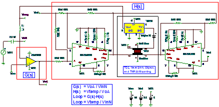
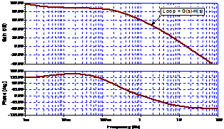
The outer loop is defined as a path around the G(s) and H(s) blocks. The goal of the simulation using Figure 1 is to interrupt the outer loop and obtain H(s), G(s), and the overall loop gain to verify the thermal loop stability. In this case, Figure 2 shows that the phase drops below zero degrees and the loop gain becomes 0 dB, which indicates that the entire loop is unstable. Therefore, changing G(s) should strengthen the PID control and increase the stability of the thermal loop.

Figure 1 Simulation circuit to obtain loop gain and phase

Figure 2 Loop gain and phase plots for Figure 1
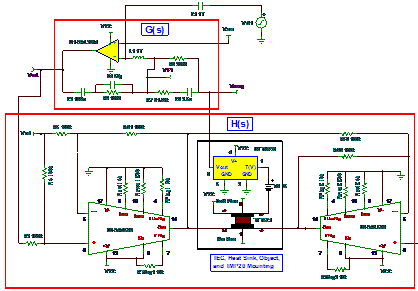
The improved G(s) module in Figure 3 includes a PID component. The angular frequency of the differential circuit is set by R7 and C3; R3 sets the proportional gain; C2 and R6 set the angular frequency of the integral circuit. [page]

Figure 3 Simulation circuit to compensate G(s)
Step 3: Break the G(s) “inner loop” to determine local amplifier stability
The final step in building a complete PID assembly is to break the inner loop and check the stability of the local amplifier (OPA2314) to ensure that its stability is independent of the overall loop gain. In this case, the amplifier requires a 50 pF capacitor (see Figure 4) to maintain stable operation of the local loop.

Figure 4 Final circuit of compensated local G(s) loop
Next time, we will discuss a bad design of a 20W amplifier that ruins a 100W speaker.
References
“Op Amp Stability, Part 2 of 15: SPICE Analysis of Op Amp Networks”, Green, Timothy, published in En-Genius (formerly Analog Zone) 2006. “
PSPICE Compatible Equivalent Circuit of Thermoelectric Coolers”, Simon Lenvkin, Sam Ben-Yaakov, published in PESC'05. IEEE 36th 2005. “ SPICE
Models of Thermoelectric Components Including Thermal Effects”, Chavez, JA, Salazar, J, Ortega, JA, and Garcia, MJ, published in Proceedings of the 17th IEEE Conference on Instrumentation Test and Measurement Technology 2000.
Reference address:Designing TEC Temperature Loop PID Control Using SPICE
Step 1: Determine the TEC/Temp sensor thermal impedance for the SPICE model.
To use SPICE as an effective tool for PID loop design, it is important to obtain the thermal response of the temperature loop in order to obtain the actual thermistor resistance, capacitance, and transfer function of the PCB à TEC à laser diode à temperature sensor wiring. Remember that since the actual thermal characteristics can vary by up to 50%, it is best to inject a thermal step input into the actual system and measure it to obtain the best thermal model for SPICE simulation.
If the thermal connection line is described, use the "Outer Loop, Inner Loop" procedure to determine the overall loop response and stability of the control amplifier in the G(s) block. In all cases, a very large inductor is used to interrupt the outer and inner loops, and the loops are excited by a large capacitor and AC power supply.
Step 2: Interrupt the Outer Loop Between G(s) and H(s)
The outer loop is defined as a path around the G(s) and H(s) blocks. The goal of the simulation using Figure 1 is to interrupt the outer loop and obtain H(s), G(s), and the overall loop gain to verify the thermal loop stability. In this case, Figure 2 shows that the phase drops below zero degrees and the loop gain becomes 0 dB, which indicates that the entire loop is unstable. Therefore, changing G(s) should strengthen the PID control and increase the stability of the thermal loop.

Figure 1 Simulation circuit to obtain loop gain and phase

Figure 2 Loop gain and phase plots for Figure 1
The improved G(s) module in Figure 3 includes a PID component. The angular frequency of the differential circuit is set by R7 and C3; R3 sets the proportional gain; C2 and R6 set the angular frequency of the integral circuit. [page]

Figure 3 Simulation circuit to compensate G(s)
Step 3: Break the G(s) “inner loop” to determine local amplifier stability
The final step in building a complete PID assembly is to break the inner loop and check the stability of the local amplifier (OPA2314) to ensure that its stability is independent of the overall loop gain. In this case, the amplifier requires a 50 pF capacitor (see Figure 4) to maintain stable operation of the local loop.

Figure 4 Final circuit of compensated local G(s) loop
Next time, we will discuss a bad design of a 20W amplifier that ruins a 100W speaker.
References
“Op Amp Stability, Part 2 of 15: SPICE Analysis of Op Amp Networks”, Green, Timothy, published in En-Genius (formerly Analog Zone) 2006. “
PSPICE Compatible Equivalent Circuit of Thermoelectric Coolers”, Simon Lenvkin, Sam Ben-Yaakov, published in PESC'05. IEEE 36th 2005. “ SPICE
Models of Thermoelectric Components Including Thermal Effects”, Chavez, JA, Salazar, J, Ortega, JA, and Garcia, MJ, published in Proceedings of the 17th IEEE Conference on Instrumentation Test and Measurement Technology 2000.
Previous article:Test Automation for 3D Integrated Systems
Next article:Building a resistance network test system based on 2400 series digital source meter
Recommended Content
Latest Test Measurement Articles
- Keysight Technologies Helps Samsung Electronics Successfully Validate FiRa® 2.0 Safe Distance Measurement Test Case
- From probes to power supplies, Tektronix is leading the way in comprehensive innovation in power electronics testing
- Seizing the Opportunities in the Chinese Application Market: NI's Challenges and Answers
- Tektronix Launches Breakthrough Power Measurement Tools to Accelerate Innovation as Global Electrification Accelerates
- Not all oscilloscopes are created equal: Why ADCs and low noise floor matter
- Enable TekHSI high-speed interface function to accelerate the remote transmission of waveform data
- How to measure the quality of soft start thyristor
- How to use a multimeter to judge whether a soft starter is good or bad
- What are the advantages and disadvantages of non-contact temperature sensors?
MoreSelected Circuit Diagrams
MorePopular Articles
- Innolux's intelligent steer-by-wire solution makes cars smarter and safer
- 8051 MCU - Parity Check
- How to efficiently balance the sensitivity of tactile sensing interfaces
- What should I do if the servo motor shakes? What causes the servo motor to shake quickly?
- 【Brushless Motor】Analysis of three-phase BLDC motor and sharing of two popular development boards
- Midea Industrial Technology's subsidiaries Clou Electronics and Hekang New Energy jointly appeared at the Munich Battery Energy Storage Exhibition and Solar Energy Exhibition
- Guoxin Sichen | Application of ferroelectric memory PB85RS2MC in power battery management, with a capacity of 2M
- Analysis of common faults of frequency converter
- In a head-on competition with Qualcomm, what kind of cockpit products has Intel come up with?
- Dalian Rongke's all-vanadium liquid flow battery energy storage equipment industrialization project has entered the sprint stage before production
MoreDaily News
- Allegro MicroSystems Introduces Advanced Magnetic and Inductive Position Sensing Solutions at Electronica 2024
- Car key in the left hand, liveness detection radar in the right hand, UWB is imperative for cars!
- After a decade of rapid development, domestic CIS has entered the market
- Aegis Dagger Battery + Thor EM-i Super Hybrid, Geely New Energy has thrown out two "king bombs"
- A brief discussion on functional safety - fault, error, and failure
- In the smart car 2.0 cycle, these core industry chains are facing major opportunities!
- The United States and Japan are developing new batteries. CATL faces challenges? How should China's new energy battery industry respond?
- Murata launches high-precision 6-axis inertial sensor for automobiles
- Ford patents pre-charge alarm to help save costs and respond to emergencies
- New real-time microcontroller system from Texas Instruments enables smarter processing in automotive and industrial applications
Guess you like
- Has anyone seen an MSP430 MCU powered directly by 5V?
- May I ask if Mr. Yi Zhongtian mentioned in a certain program that he talked about "have you learned it?", "have you learned it thoroughly?", "have you learned it thoroughly?", in which program did he say this?
- Is it as shown in the picture?
- PCB file conversion
- 5G indoor base stations will be released soon, and it is expected that each household will have a small base station, which will subvert the existing home Internet access methods.
- How to consider the impact of audio analog signals after being transmitted through a 100m long cable?
- Angle sensor
- Transistor Selection
- NUCLEO_G431RB Review - RTC Real-time Clock
- 【New Year's Taste Competition】+ Spring Festival Customs

 Signal Integrity and Power Integrity Analysis (Eric Bogatin)
 Refrigeration component requirements


 京公网安备 11010802033920号