0 Introduction
LTE (Long Term Evolution) technology is the main direction of the evolution of the third generation of mobile communications. As an advanced technology, the LTE system has great advantages in improving peak data rate, cell edge rate, spectrum utilization, control plane and user plane latency, and reducing operation and network construction costs. At the same time, the LTE system can coexist with the existing system (2G/2.5G/3G) and achieve smooth evolution. The LTE
system is divided into frequency division duplex (FDD) and time division duplex (TDD) according to the duplex mode. Among them, the LTE-TDD standard has many advantages over the FDD standard, such as flexible spectrum utilization and support for asymmetric services. It is an international standard promoted by the Chinese communications industry.
System throughput is an important indicator to measure the comprehensive performance of TD-LTE base stations. The throughput test requires real-time feedback and dynamic adjustment between the base station (eNB) and the test instrument (simulated UE). The test instrument not only needs to be able to generate TD-LTE uplink signals that meet the 3GPP standard, but also needs to simulate the corresponding channel fading model and adjust the coding redundancy factor of the transmitted signal in real time according to the ACK/NACK instructions sent by the base station to simulate the real communication environment. This solution uses Agilent's baseband signal generator and channel emulator N5106A PXB or Agilent's latest signal generator N5182B/N5172B as the test platform. The TD-LTE test signal is generated by the Real-time version of Signal Studio N7625 for LTE TDD and sent to the base station for decoding after channel fading, so that the base station throughput can be counted.
1 HARQ Test Principle
1.1 Uplink HARQ Method
The LTE system will use synchronous non-adaptive HARQ technology in the uplink. Although asynchronous adaptive HARQ technology has higher scheduling flexibility than synchronous non-adaptive technology, the latter requires less signaling overhead. Due to the complexity of the uplink, the interference from users in other cells is uncertain, so the base station cannot accurately estimate the actual signal-to-interference ratio (SINR) value of each user. Due to the inaccuracy of SINR values, the uplink selection of modulation and coding mode (MCS) is not accurate enough, so the HARQ technology is more relied on to ensure the performance of the system. Therefore, the average transmission number of the uplink will be higher than that of the downlink. Therefore, considering the overhead of control signaling, synchronous non-adaptive HARQ technology is used in the uplink.
1.2 Uplink HARQ timing
The uplink and downlink signals of the LTE TDD standard are staggered in the time domain, so its HARQ timing mapping relationship is more complicated than that of FDD. According to 3GPP TS 36.213, under different UL/DL Configurations of the TDD standard, the downlink subframe only sends ACK/NACK instructions at the specified position, and the ACK/NACK instructions sent at each position correspond to a specific uplink subframe signal, as shown in Table 1.
Table 1 TD-LTE HARQ uplink and downlink subframe mapping relationship

3GPP TS 36.141 stipulates that performance testing only needs to be performed under configuration 1, so the timing diagram for configuration 1 can be obtained according to the description in Table 1:

Figure 1 HARQ timing diagram for configuration 1
In configuration 1, the uplink only sends uplink signals in subframes 2, 3, 7 and 8; the base station sends ACK/NACK instructions in subframes 1, 4, 6 and 9 for the downlink. The instruction object and retransmission position relationship are shown in Figure 1.
2 Test platform
2.1 Hardware platform
The purpose of performance testing is to simulate the system throughput in the actual environment, so the base station and the test instrument need to be jointly debugged. The hardware test platform includes: TD-LTE eNB base station supporting 2-antenna reception, Agilent baseband signal generator and channel emulator PXB, Agilent vector signal generator MXG (mainly used for up-conversion) and a four-channel oscilloscope (for system debugging). The test system structure is as follows:
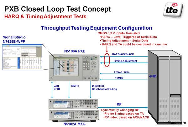
Figure 2 N5106 PXB test system
PXB generates TD-LTE uplink signals in real time and after fading under a specific channel model, the output baseband I/Q signals are up-converted by MXG and sent to the two receiving antennas of the base station. The base station demodulates and decodes the received RF signals and transmits the feedback results (ACK/NACK instructions) back to PXB in RS232C serial communication mode. PXB adjusts the RV factor in real time according to the ACK/NACK instructions to resend the data packet or choose to abandon the current data packet (when the eNB sends an ACK signal or the maximum number of retransmissions has been reached). Finally, the base station obtains the system throughput by statistics.
If the test environment really wants to use an external channel emulator, you only need to use the Agilent N5182B/N5172B RF signal generator to complete the test of the above system. The typical measurement system is shown in Figure 3.
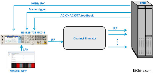
Figure 3 N5182B/72B MXG-B test system
2.2 Software platform
PXB or N5182B/72B generates specific reference test signals through Signal Studio N7625B-WFP for LTE TDD software and adjusts the coding redundancy factor in real time. [page]
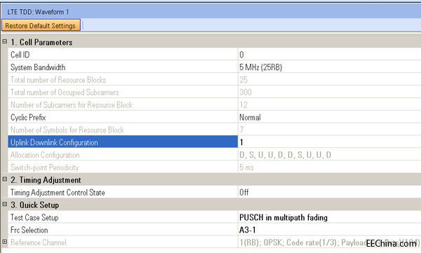
Figure 4 Uplink signal configuration
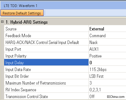
Figure 5 HARQ setting
2.3 Feedback signal format
The ACK/NACK signal sent by the base station to PXB or N5182B/72B is encoded in the data format of RS232C serial communication. PXB or N5182B/72B decodes the ACK/NACK value according to the same coding rate and format. The feedback signal consists of 8 bits, 1 start bit, 1 stop bit, and no parity bit. The specific data format is shown in Table 2.
Table 2 ACK/NACK encoding format (LSB)

3 Test results
Build the test system and configure the software platform according to the test structure diagram, start the base station and PXB or N5182B/72B, and observe the test results on the oscilloscope and base station control terminal.
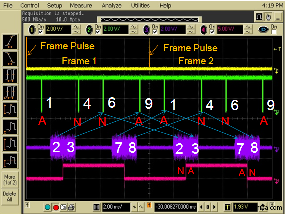
Figure 6 PXB or N5182B/72B real-time response
Figure 6 shows the real-time response of PXB or N5182B/72B observed on the oscilloscope. Channels 1, 2, 3 and 4 are the uplink signal frame header, ACK/NACK instruction sequence, uplink signal I/Q data and ACK/NACK response of PXB or N5182B/72B (high level is ACK, low level is NACK). As shown in the figure, the HARQ timing response is completely consistent with the standard protocol. The
base station performs diversity reception and demodulation on the uplink RF signal, and then judges the reception result through CRC check, and finally obtains the system throughput under a specific fading model.
According to 3GPP TS 36.141, PUSCH, 20MHz bandwidth signal is selected as the test case. Under 2 receiving antennas and Normal CP, the first 10 cases listed are tested in turn, and the results are as follows:
Table 3 PUSCH, PUSCH performance test results under 20MHz bandwidth

4 Conclusion
The results show that the system fully meets the standard test requirements. The test process is transparent and the results are intuitive and reliable. At the same time, the test system can achieve 1×2, 2×2, 2×4 and 4×2 MIMO configurations through software configuration without adding any hardware configuration, thereby realizing base station HARQ, Timing Adjustment and PUCCH performance testing, which is an ideal platform for TD-LTE base station performance testing.
Keywords:HARQ TD-LTE
Reference address:TD-LTE base station performance testing techniques based on HARQ
LTE (Long Term Evolution) technology is the main direction of the evolution of the third generation of mobile communications. As an advanced technology, the LTE system has great advantages in improving peak data rate, cell edge rate, spectrum utilization, control plane and user plane latency, and reducing operation and network construction costs. At the same time, the LTE system can coexist with the existing system (2G/2.5G/3G) and achieve smooth evolution. The LTE
system is divided into frequency division duplex (FDD) and time division duplex (TDD) according to the duplex mode. Among them, the LTE-TDD standard has many advantages over the FDD standard, such as flexible spectrum utilization and support for asymmetric services. It is an international standard promoted by the Chinese communications industry.
System throughput is an important indicator to measure the comprehensive performance of TD-LTE base stations. The throughput test requires real-time feedback and dynamic adjustment between the base station (eNB) and the test instrument (simulated UE). The test instrument not only needs to be able to generate TD-LTE uplink signals that meet the 3GPP standard, but also needs to simulate the corresponding channel fading model and adjust the coding redundancy factor of the transmitted signal in real time according to the ACK/NACK instructions sent by the base station to simulate the real communication environment. This solution uses Agilent's baseband signal generator and channel emulator N5106A PXB or Agilent's latest signal generator N5182B/N5172B as the test platform. The TD-LTE test signal is generated by the Real-time version of Signal Studio N7625 for LTE TDD and sent to the base station for decoding after channel fading, so that the base station throughput can be counted.
1 HARQ Test Principle
1.1 Uplink HARQ Method
The LTE system will use synchronous non-adaptive HARQ technology in the uplink. Although asynchronous adaptive HARQ technology has higher scheduling flexibility than synchronous non-adaptive technology, the latter requires less signaling overhead. Due to the complexity of the uplink, the interference from users in other cells is uncertain, so the base station cannot accurately estimate the actual signal-to-interference ratio (SINR) value of each user. Due to the inaccuracy of SINR values, the uplink selection of modulation and coding mode (MCS) is not accurate enough, so the HARQ technology is more relied on to ensure the performance of the system. Therefore, the average transmission number of the uplink will be higher than that of the downlink. Therefore, considering the overhead of control signaling, synchronous non-adaptive HARQ technology is used in the uplink.
1.2 Uplink HARQ timing
The uplink and downlink signals of the LTE TDD standard are staggered in the time domain, so its HARQ timing mapping relationship is more complicated than that of FDD. According to 3GPP TS 36.213, under different UL/DL Configurations of the TDD standard, the downlink subframe only sends ACK/NACK instructions at the specified position, and the ACK/NACK instructions sent at each position correspond to a specific uplink subframe signal, as shown in Table 1.
Table 1 TD-LTE HARQ uplink and downlink subframe mapping relationship

3GPP TS 36.141 stipulates that performance testing only needs to be performed under configuration 1, so the timing diagram for configuration 1 can be obtained according to the description in Table 1:

Figure 1 HARQ timing diagram for configuration 1
In configuration 1, the uplink only sends uplink signals in subframes 2, 3, 7 and 8; the base station sends ACK/NACK instructions in subframes 1, 4, 6 and 9 for the downlink. The instruction object and retransmission position relationship are shown in Figure 1.
2 Test platform
2.1 Hardware platform
The purpose of performance testing is to simulate the system throughput in the actual environment, so the base station and the test instrument need to be jointly debugged. The hardware test platform includes: TD-LTE eNB base station supporting 2-antenna reception, Agilent baseband signal generator and channel emulator PXB, Agilent vector signal generator MXG (mainly used for up-conversion) and a four-channel oscilloscope (for system debugging). The test system structure is as follows:

Figure 2 N5106 PXB test system
PXB generates TD-LTE uplink signals in real time and after fading under a specific channel model, the output baseband I/Q signals are up-converted by MXG and sent to the two receiving antennas of the base station. The base station demodulates and decodes the received RF signals and transmits the feedback results (ACK/NACK instructions) back to PXB in RS232C serial communication mode. PXB adjusts the RV factor in real time according to the ACK/NACK instructions to resend the data packet or choose to abandon the current data packet (when the eNB sends an ACK signal or the maximum number of retransmissions has been reached). Finally, the base station obtains the system throughput by statistics.
If the test environment really wants to use an external channel emulator, you only need to use the Agilent N5182B/N5172B RF signal generator to complete the test of the above system. The typical measurement system is shown in Figure 3.

Figure 3 N5182B/72B MXG-B test system
2.2 Software platform
PXB or N5182B/72B generates specific reference test signals through Signal Studio N7625B-WFP for LTE TDD software and adjusts the coding redundancy factor in real time. [page]

Figure 4 Uplink signal configuration

Figure 5 HARQ setting
2.3 Feedback signal format
The ACK/NACK signal sent by the base station to PXB or N5182B/72B is encoded in the data format of RS232C serial communication. PXB or N5182B/72B decodes the ACK/NACK value according to the same coding rate and format. The feedback signal consists of 8 bits, 1 start bit, 1 stop bit, and no parity bit. The specific data format is shown in Table 2.
Table 2 ACK/NACK encoding format (LSB)

3 Test results
Build the test system and configure the software platform according to the test structure diagram, start the base station and PXB or N5182B/72B, and observe the test results on the oscilloscope and base station control terminal.

Figure 6 PXB or N5182B/72B real-time response
Figure 6 shows the real-time response of PXB or N5182B/72B observed on the oscilloscope. Channels 1, 2, 3 and 4 are the uplink signal frame header, ACK/NACK instruction sequence, uplink signal I/Q data and ACK/NACK response of PXB or N5182B/72B (high level is ACK, low level is NACK). As shown in the figure, the HARQ timing response is completely consistent with the standard protocol. The
base station performs diversity reception and demodulation on the uplink RF signal, and then judges the reception result through CRC check, and finally obtains the system throughput under a specific fading model.
According to 3GPP TS 36.141, PUSCH, 20MHz bandwidth signal is selected as the test case. Under 2 receiving antennas and Normal CP, the first 10 cases listed are tested in turn, and the results are as follows:
Table 3 PUSCH, PUSCH performance test results under 20MHz bandwidth

4 Conclusion
The results show that the system fully meets the standard test requirements. The test process is transparent and the results are intuitive and reliable. At the same time, the test system can achieve 1×2, 2×2, 2×4 and 4×2 MIMO configurations through software configuration without adding any hardware configuration, thereby realizing base station HARQ, Timing Adjustment and PUCCH performance testing, which is an ideal platform for TD-LTE base station performance testing.
Previous article:Exploring RF interference in complex RF environments
Next article:NI offers a better solution for spectrum monitoring
Latest Test Measurement Articles
- Keysight Technologies Helps Samsung Electronics Successfully Validate FiRa® 2.0 Safe Distance Measurement Test Case
- From probes to power supplies, Tektronix is leading the way in comprehensive innovation in power electronics testing
- Seizing the Opportunities in the Chinese Application Market: NI's Challenges and Answers
- Tektronix Launches Breakthrough Power Measurement Tools to Accelerate Innovation as Global Electrification Accelerates
- Not all oscilloscopes are created equal: Why ADCs and low noise floor matter
- Enable TekHSI high-speed interface function to accelerate the remote transmission of waveform data
- How to measure the quality of soft start thyristor
- How to use a multimeter to judge whether a soft starter is good or bad
- What are the advantages and disadvantages of non-contact temperature sensors?
MoreSelected Circuit Diagrams
MorePopular Articles
- Innolux's intelligent steer-by-wire solution makes cars smarter and safer
- 8051 MCU - Parity Check
- How to efficiently balance the sensitivity of tactile sensing interfaces
- What should I do if the servo motor shakes? What causes the servo motor to shake quickly?
- 【Brushless Motor】Analysis of three-phase BLDC motor and sharing of two popular development boards
- Midea Industrial Technology's subsidiaries Clou Electronics and Hekang New Energy jointly appeared at the Munich Battery Energy Storage Exhibition and Solar Energy Exhibition
- Guoxin Sichen | Application of ferroelectric memory PB85RS2MC in power battery management, with a capacity of 2M
- Analysis of common faults of frequency converter
- In a head-on competition with Qualcomm, what kind of cockpit products has Intel come up with?
- Dalian Rongke's all-vanadium liquid flow battery energy storage equipment industrialization project has entered the sprint stage before production
MoreDaily News
- Allegro MicroSystems Introduces Advanced Magnetic and Inductive Position Sensing Solutions at Electronica 2024
- Car key in the left hand, liveness detection radar in the right hand, UWB is imperative for cars!
- After a decade of rapid development, domestic CIS has entered the market
- Aegis Dagger Battery + Thor EM-i Super Hybrid, Geely New Energy has thrown out two "king bombs"
- A brief discussion on functional safety - fault, error, and failure
- In the smart car 2.0 cycle, these core industry chains are facing major opportunities!
- Rambus Launches Industry's First HBM 4 Controller IP: What Are the Technical Details Behind It?
- The United States and Japan are developing new batteries. CATL faces challenges? How should China's new energy battery industry respond?
- Murata launches high-precision 6-axis inertial sensor for automobiles
- Ford patents pre-charge alarm to help save costs and respond to emergencies
Guess you like
- [RVB2601 Creative Application Development] Three-in-one OLED display for calendar, time, temperature and humidity
- GD32E103 eval board download error
- EEWORLD University - Brushless Motor Tutorial
- Introduction to FPGA design process and tool software
- How to deal with the inductor spike at the back end of the switching power supply
- The development of 3G in China
- EEWORLD University----[High Precision Laboratory] Interface: RS-485
- Newbie, please help me with CPLD frequency multiplication
- Are there any netizens working in the field of motors?
- Evaluation report summary: Mir MYS-8MMX

 Mobile Communications (Li Zhaoyu)
 LTE Tutorial: Architecture and Implementation


 京公网安备 11010802033920号