1. Introduction
The AC speed control system usually uses IGBT pulse width modulation drivers to control the execution motor to operate in four quadrants, so as to meet the high precision and high real-time requirements of the control system. The driver is the core part of the AC speed control unit in the control system, and its quality and performance directly affect the accuracy and performance of the entire control system. However, during use, once the driver fails, it will affect the normal operation of the entire control system. Therefore, it is necessary to design and develop a comprehensive performance test system for the driver to quickly troubleshoot and ensure the performance quality of the control system.
2. Driver working principle and test system technical features 
Figure 1: Principle block diagram of the driver speed control system
The drive speed control can generally be divided into four parts: rectification, DC holding, inversion and control. The current regulator compares the actual current value with the given value and adjusts it. The speed regulator obtains the actual speed value through the speed measuring motor and rotor position detection, and adjusts the speed value.
The driver is a high-power precision device, which may interfere with the outside world and affect normal operation. The noise signals generated by other devices on the same power supply may also enter the driver through radiation and power supply conduction. At the same time, the high-order harmonics and radio noise generated by the driver are also easy to affect the power grid and peripheral equipment. Eliminating interference and making the equipment work normally is a major feature of this system, but also a difficulty. The design adopts a standard grounding method, and connects a filter device to the front and rear ends of the driver. The circuit is connected in series with an inrush current limiting circuit to effectively avoid mutual interference and make each test signal accurate and reliable.
The test system adopts two test methods: online or offline. The software realizes the function of the intelligent processing module, and the expert system provides solutions for the test problems.
3. Hardware circuit implementation of the driver test system
The test system mainly includes a test and control station with a computer as the core and a test platform for installing the driver to be tested, simulated loads, special measuring instruments and other equipment. The circuit design adopts pulse diagnosis anti-interference and redundant design to ensure that the hardware design is accurate and reliable. The specific connection diagram is as follows: 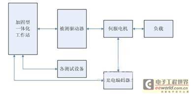
Figure 2: Driver test system connection diagram
3.1 Startup circuit
The startup circuit provides the working voltage for the driver to be tested. Three current limiting resistors are connected in series in the circuit to prevent inrush current. At the same time, the contactor, thermal relay and filter ensure the stable and reliable quality of the provided voltage. During the power-on process, it is only necessary to control the computer to issue a power-on command, the contactor acts, and the power-on process is completed to achieve a safe and reliable "soft start". The schematic diagram of the startup circuit is shown below. 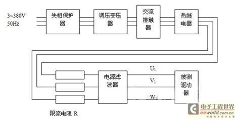
Figure 3: Schematic diagram of the startup circuit
3.2 Enable and detection circuit
To ensure that the driver under test is in a controllable state, the pulse enable and drive enable of the driver under test are controlled through the software interface. At the same time, the enable state is displayed on the display interface to make the operation more intuitive.
The driver is powered on and enabled to communicate through the serial port, and the driver working state is detected in real time through the serial port. The serial port communication uses the communication card PCL745, which has strong anti-interference ability through differential input, and does not need to add 232 or 485 conversion modules, and can directly communicate with the ADAM module. The specific connection diagram is as follows. 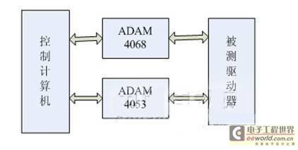
Figure 4: Enable and detection module connection diagram
4. Test system software features
The test system software is compiled in accordance with the requirements of software engineering, and strives to be powerful, stable and reliable. At the same time, the software is expanded and has expert system functions.
4.1 Human-computer interaction interface
The interface is the manifestation of the test system and is a window for users to analyze and judge. Users can set self-test items and test items, and can also print and diagnose faults. In the human-computer interaction interface, the items to be tested are set, and the computer sends speed instructions to the drive under test. The test software performs online analysis and comparison of the data obtained through the dedicated interface and other test equipment, and gives a qualified conclusion. At the same time, the knowledge of the expert diagnosis knowledge base is called for fault diagnosis, and a solution to the fault is given. The composition of the human-computer interaction interface module is shown in Figure 5. [page] 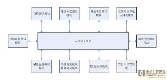
Figure 5: Human-computer interaction interface module Figure
4.2 Test system dynamic link library
The test system dynamic link library uses the standard access method ODBC (Open Database Connectivity) to establish a set of dynamic link libraries DLL, namely the drive basic information library and the special machine diagnosis knowledge base. The main content of the drive basic information library is the drive technical parameters, and the expert diagnosis knowledge base is mainly the analysis of typical drive faults. If the user needs to expand the expert diagnosis knowledge base content, it can be added through the human-computer interface.
4.2 Important project tests
4.2.1 External current limit reduction test
When a -10V voltage is added to the XX end of the drive under test, the overcurrent monitoring function of the speed controller loses its function. According to the current reduction characteristic curve, it can be seen that the maximum output current is limited to 40%Imax. The speed setting value is set to -5V, the drive enable is turned on for 3 minutes and then turned off, and the waveform of the detection hole is measured. The Iist amplitude should be 4+0.4V, and the "overcurrent" indicator light is not on. The current reduction characteristic curve is shown in Figure 6. 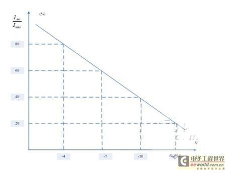
Figure 6: Current reduction characteristic curve
4.2.2 I2t monitoring test
The I2t function approximates the square of the actual current value and then integrates the result. If the actual current value is 1.1 times the rated value, the integrator integrates negatively, otherwise it integrates positively.
The specific test uses a test power board to replace the power module of the driver, turns off the corresponding switch, and adds a -1V voltage to the XX terminal. From the XX characteristic curve, it can be seen that the maximum output current is 100%'Imax. In this test interface, the speed setting is set to -5V, the drive enable is turned on, and the W hole Iist waveform is measured. The recorded data is input into the corresponding unit. The background software can give a qualified conclusion through calculation (the final trend of the Iist amplitude decrease should be 1.1IN, and the maximum amplitude holding time T should be).
5. Conclusion
The drive test system can test the drive in both offline and online states. The test system can help the debugging personnel quickly determine and understand the drive status during debugging or use, and propose solutions. The operation is simple and fast, and the human-computer interaction is good. The system follows the principles of universalization, standardization and modular design, and has good interactivity, portability and scalability. The design of this test system has been completed, which has greatly facilitated the maintenance of the drive. At the same time, the portable drive test system is also under research and design and will be completed soon.
Previous article:Two Synchronization Methods for Motion Control and Data Acquisition in Test Systems
Next article:Application of CPLD in Cable Rapid Testing Technology
- Popular Resources
- Popular amplifiers
- From probes to power supplies, Tektronix is leading the way in comprehensive innovation in power electronics testing
- Seizing the Opportunities in the Chinese Application Market: NI's Challenges and Answers
- Tektronix Launches Breakthrough Power Measurement Tools to Accelerate Innovation as Global Electrification Accelerates
- Not all oscilloscopes are created equal: Why ADCs and low noise floor matter
- Enable TekHSI high-speed interface function to accelerate the remote transmission of waveform data
- How to measure the quality of soft start thyristor
- How to use a multimeter to judge whether a soft starter is good or bad
- What are the advantages and disadvantages of non-contact temperature sensors?
- In what situations are non-contact temperature sensors widely used?
- LED chemical incompatibility test to see which chemicals LEDs can be used with
- Application of ARM9 hardware coprocessor on WinCE embedded motherboard
- What are the key points for selecting rotor flowmeter?
- LM317 high power charger circuit
- A brief analysis of Embest's application and development of embedded medical devices
- Single-phase RC protection circuit
- stm32 PVD programmable voltage monitor
- Introduction and measurement of edge trigger and level trigger of 51 single chip microcomputer
- Improved design of Linux system software shell protection technology
- What to do if the ABB robot protection device stops
- Huawei's Strategic Department Director Gai Gang: The cumulative installed base of open source Euler operating system exceeds 10 million sets
- Download from the Internet--ARM Getting Started Notes
- Learn ARM development(22)
- Learn ARM development(21)
- Learn ARM development(20)
- Learn ARM development(19)
- Learn ARM development(14)
- Learn ARM development(15)
- Analysis of the application of several common contact parts in high-voltage connectors of new energy vehicles
- Wiring harness durability test and contact voltage drop test method
- 【National Technology N32G430】Review ~ PWM
- How are the low drive capability and high drive capability of the pin drive capability register PDDR realized?
- [Mill Edge AI Computing Box FZ5 Review] First experience with "image recognition"
- EnDat 2.2 Absolute Encoder Master Interface Reference Design for C2000 MCUs
- 10 PCB heat dissipation methods, understand them in one article!
- STC15 series gpio problem
- Design of temperature detector based on MSP430F149
- RSL10 Data Set
- Could you please tell me which category this photoelectric switch belongs to?
- Regarding chip thermal calculations, this article is worth reading!

 5962-8863002VX


 京公网安备 11010802033920号