Introduction
With the development of society, people in the 21st century pay more and more attention to safety issues, especially medical and medical safety issues. At present, hospitals generally use nurses to monitor patients for infusion, or patients' families to monitor. In this case, once the manual monitoring is not in place, it may cause the gas in the bottled infusion to enter the human body through the infusion pipeline after the liquid is infused, which is usually called gas embolism, causing serious physical harm to the patient or even death. The infusion alarm device can solve this problem. Infusion alarms in society use various principles and production methods. The main test method is to use a pressure sensor to measure the gravity of the liquid in the bottle, and then convert the physical quantity of gravity into the physical quantity of the height of the liquid in the bottle. This method has clear and simple ideas, but it is difficult to operate. This is mainly because the liquid in the bottle is generally not a pure substance, and the density is difficult to determine; in addition, whether the liquid in the bottle is mixed evenly is also an important factor affecting the measurement, so this method is actually not advisable.
Using the principle of rectilinear propagation and refraction of light, an infrared probe is used to illuminate the liquid surface and a corresponding receiving device is used to receive the signal. The liquid surface is detected and an alarm is sounded based on the received analog signal. The device is simple, but the accuracy is not high due to the refraction, scattering and transmission of light. The method of using infrared sensors loaded on both ends of the infusion tube to record the number of drops is not only simple in device and principle, but also highly accurate. Most importantly, it is low in cost and portable, which is convenient for nurses to disassemble and use drugs and does not pollute drugs, achieving non-contact measurement, which solves the problem of infusion alarms well, reduces the time and energy of medical staff, and ensures the safety of patients.
1 Design principle and method
1.1 Design principle
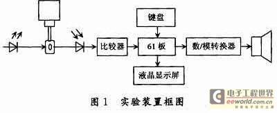
This design principle mainly uses the measurement of the number of falling water drops to determine the height of the liquid level and alarm. Its working principle is as follows: water is dripped down through the infusion device, and an infrared light-emitting diode and a photosensitive diode are placed on both sides of the dropper of the infusion tube. When water drops, the light received by the photosensitive diode will decrease, resulting in an increase in the voltage across the photosensitive diode. The voltage is compared with the initial voltage set by the voltage comparator, and the voltage comparator will convert between high and low levels. By recording the number of conversions, the number of drops of falling water can be determined, thereby determining the liquid level and realizing the alarm function. The
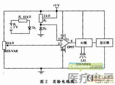
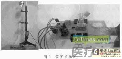
experimental device block diagram is shown in Figure 1, the circuit diagram is shown in Figure 2, and the actual picture is shown in Figure 3.
1.2 Basic process and method of the experiment
In the production process, fill the Coke bottle with water and fix it upside down on the Joules scale. The Joules scale is used to fix the instrument, and the dropper is connected to make the water droplets fall one by one. At the same time, make the infrared light-emitting diode, photosensitive diode and water droplets in the same straight line, turn on the water drop control switch to make the liquid fall. When the water droplets fall, the voltage signal at the receiving end of the infrared sensor is amplified, and the high and low levels are output through the comparator to program the microcontroller to count, and it is displayed on the LCD screen. When the experiment starts, use the button to set the alarm point. When the number of drops counted by the counter reaches the alarm point, the alarm sounds.
The 61 board is a 16-bit microcontroller planned by Lingyang University, and its core chip is SPCE061A.
SPCE061A is another 16-bit microcontroller launched by Lingyang Technology after the μ'nSPTM series products SPCE500A and others. Unlike SPCE500A, SPCE061A has only 32 KB of flash memory (FLASH) built in, considering the user's need for less resources and the convenience of program debugging. The higher processing speed enables μ'nSPTM to process complex digital signals very easily and quickly. Therefore, compared with SPCE500A, SPCE061A microcontroller with μ'nSPTM as the core is the most economical choice for products in the field of digital speech recognition applications. The performance is as follows: 16-bit μ'nSPTM microprocessor; operating voltage (CPU) VDD is 2.4~3.6 V (I/O); CPU clock: 0.32~49.152 MHz, built-in 2 KB SRAM, 32 KBFLASH, programmable audio processing.
The display screen is 4×8 lcd12864.
LS1 is an 8 Ω 0.5 W speaker.
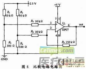
The operational amplifier is OP07. The OP07 chip is a low-noise, non-chopper-stabilized bipolar operational amplifier integrated circuit. The comparison circuit composed of the operational amplifier is shown in Figure 4. Since the OP07 has a very low input offset voltage (maximum 25μV for OP07A), the OP07 does not require additional zeroing measures in many applications. The OP07 also has the characteristics of low input bias current (±2 nA for OP07A) and high open-loop gain (300V/mV for OP07A). This low offset and high open-loop gain feature makes the OP07 particularly suitable for high-gain measurement equipment and amplifying weak signals of sensors.
Ultra-low offset: 150μV maximum; low input bias current: 1.8nA; low offset voltage drift 0.5μV/℃; ultra-stable, time: 2μV/month maximum; high power supply voltage range: -3~-22 V, +3~+22 V.
1.3 Software Flow in the Microcontroller
The software flow chart in the microcontroller is shown in Figure 5.
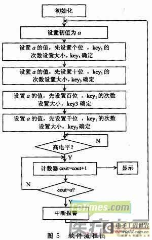
Initialize first, then set the initial value a by pressing the key. If the voltage at the signal receiving end is high, the counter cout=cout+1, if it is low, it will not be added. When the counter cout is equal to the initial value a, the alarm is interrupted and then reinitialized. If it is not equal to the initial value, the counting continues. The counting process is displayed in real time on the LCD panel. [page]
1.4 List of components used in the production
The components used in the production are as follows:
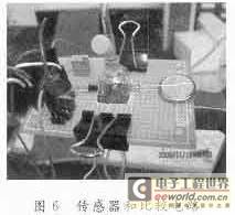
photodiode GKF104, infrared emitting tube GKF104, Lingyang 61 board SPCE061A. LCD display lcd12864 (see Figure 6), Joly scale, 5 V voltage regulator, resistor, sliding rheostat, wire, medical infusion set, 2.5 L Coke bottle.
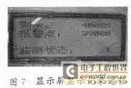
The infrared transmitting and receiving device used in the experiment of the infrared transmitting and receiving device is the GKF104 component, and the actual picture is shown in Figure 7. This component is a component that integrates infrared transmitting and receiving, which ensures that the infrared rays emitted by the infrared transmitting device can be received by its receiving device. However, during the experiment, the infrared transmitting and receiving devices are no longer on the same side, so the infrared transmitting head and the receiving head of GKF 104 are artificially separated and placed on both sides of the bottle facing each other. When the light at both ends of the infrared receiving device decreases, the voltage at both ends of it will increase. In the experiment, the infrared emitting diode is connected to the positive and negative poles of the CR2330 (3 V) button battery, with the long pin being positive and the short pin being negative.
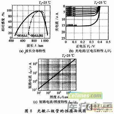
The property curve of the photodiode is shown in Figure 8.
2 Data measurement and analysis
2.1 Test data
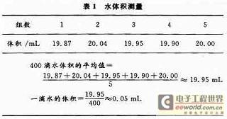
The volume of a drop of water is shown in Table 1 (first measure the volume of 400 drops of water in mL and then take the average value).
2.2 Data Analysis
The volume of a drop of water can be used to calculate the following results:
2.5 L water:
2 500/0.05 = 50 000 drops
2 L water:
2 000/0.05 = 40 000 drops
When the counter reaches the initial number of drops, the alarm starts to sound.
The reference voltage of the comparison circuit composed of OP07 is set to 4.0 V. Theoretically, the output is 5 V high level when it is greater than 4 V, and 0 V when it is less than 4 V. Due to the influence of the leakage current of the op amp, the low level is 1.1 V and the high level is 4.3 V.
2.3 Error Analysis
The circuit may have a delay in time, resulting in a certain error in the counting of water drops, but the delay is very large, so it can be ignored.
There may be bubbles in the falling water droplets, which causes the volume of a drop of water to not reach the average value of 0.05 mL, resulting in the actual volume being less than the theoretical value when the number of water drops reaches a certain amount. However, the bubbles in the water droplets come from the infusion tube, and the impact on the measurement of water droplets is not very large and can be ignored.
3 Conclusion
The main design idea of the device is to collect electrical signals for each drop of water falling through the dropper through an infrared sensor. The experimental measurement shows that the data measured by this method is relatively accurate and the error is very small. At the same time, the idea of this method is simple, intuitive and easy to understand, and can directly measure the exact amount of water remaining in the bottle. This method only collects data on water drops, which not only eliminates the errors in other links caused by cumbersome steps, but also the displayed data can be almost synchronized with the actual data without delay. The experiment shows the volume of the remaining water, which well realizes the setting of the control alarm.
Previous article:Using Resistor Noise to Characterize a Low-Noise Amplifier
Next article:Brief Analysis of Automobile Knock Sensor Test System Technology
- Popular Resources
- Popular amplifiers
- Keysight Technologies Helps Samsung Electronics Successfully Validate FiRa® 2.0 Safe Distance Measurement Test Case
- From probes to power supplies, Tektronix is leading the way in comprehensive innovation in power electronics testing
- Seizing the Opportunities in the Chinese Application Market: NI's Challenges and Answers
- Tektronix Launches Breakthrough Power Measurement Tools to Accelerate Innovation as Global Electrification Accelerates
- Not all oscilloscopes are created equal: Why ADCs and low noise floor matter
- Enable TekHSI high-speed interface function to accelerate the remote transmission of waveform data
- How to measure the quality of soft start thyristor
- How to use a multimeter to judge whether a soft starter is good or bad
- What are the advantages and disadvantages of non-contact temperature sensors?
- Innolux's intelligent steer-by-wire solution makes cars smarter and safer
- 8051 MCU - Parity Check
- How to efficiently balance the sensitivity of tactile sensing interfaces
- What should I do if the servo motor shakes? What causes the servo motor to shake quickly?
- 【Brushless Motor】Analysis of three-phase BLDC motor and sharing of two popular development boards
- Midea Industrial Technology's subsidiaries Clou Electronics and Hekang New Energy jointly appeared at the Munich Battery Energy Storage Exhibition and Solar Energy Exhibition
- Guoxin Sichen | Application of ferroelectric memory PB85RS2MC in power battery management, with a capacity of 2M
- Analysis of common faults of frequency converter
- In a head-on competition with Qualcomm, what kind of cockpit products has Intel come up with?
- Dalian Rongke's all-vanadium liquid flow battery energy storage equipment industrialization project has entered the sprint stage before production
- Allegro MicroSystems Introduces Advanced Magnetic and Inductive Position Sensing Solutions at Electronica 2024
- Car key in the left hand, liveness detection radar in the right hand, UWB is imperative for cars!
- After a decade of rapid development, domestic CIS has entered the market
- Aegis Dagger Battery + Thor EM-i Super Hybrid, Geely New Energy has thrown out two "king bombs"
- A brief discussion on functional safety - fault, error, and failure
- In the smart car 2.0 cycle, these core industry chains are facing major opportunities!
- The United States and Japan are developing new batteries. CATL faces challenges? How should China's new energy battery industry respond?
- Murata launches high-precision 6-axis inertial sensor for automobiles
- Ford patents pre-charge alarm to help save costs and respond to emergencies
- New real-time microcontroller system from Texas Instruments enables smarter processing in automotive and industrial applications
- [Sipeed LicheeRV 86 Panel Review] The board is not responding
- Use stm32l452 to drive hts221 and stts751 routine
- [National Technology N32WB452 Review] + Basic Function Usage
- Will demand for SiC FETs increase in the future?
- Problems with pressure maintenance of testing machine
- Testing a battery-powered product with a 26K resistor between the battery pads (no battery is soldered at this time!),...
- When TMS320F28377D runs CLA, it shows that Cla1Task2 does not contain frame information
- Application and precautions of Hall elements
- Which one is better to use, the Type-C interface or the MicroUSB interface for mobile phone data cables?
- Showing goods + development board and multimeter

 Real-time driver monitoring system via modal and viewpoint analysis


 京公网安备 11010802033920号