1 Introduction
Since the discovery of carbon nanotubes by Japanese professor Iijima in 1991, nanotechnology has attracted the interest and research of a large number of scientists and is currently a hot topic in the scientific community. Based on the unique electrical properties of carbon nanotubes, the idea of using carbon nanotube arrays to build new antennas and transmission lines has been proposed. Since then, relevant foreign institutions have also carried out research on the interaction between carbon nanotubes and electromagnetic waves. Using carbon nanotubes to build new electromagnetic wave transmission media and developing new antenna technology has become a hot topic in the microwave field.
Due to the ballistic transport effect and quasi-one-dimensional quantum wire characteristics, carbon nanotubes have lower ohmic loss and weaker skin effect than traditional metal tubes, and have the possibility of building new antennas. Therefore, a lot of research has been done on nanoantennas at home and abroad. The properties of a single nanotube as a dipole antenna were studied. Theoretical calculations show that the wavelength of electromagnetic waves on the nanotube is about 1/50 of the wavelength in free space, and it is possible to resonate in a lower frequency band. However, due to the high input impedance of a single carbon nanotube antenna, the antenna efficiency is too low and there is no possibility of practical application. Therefore, it is more practical to use carbon nanotube arrays to build microwave devices. It is proposed to use a midpoint-fed carbon nanotube bundle as an antenna array and use CST for simulation. The results show that the nanotube bundle is 30-40dB higher than the antenna efficiency of a single nanotube. The nanotube bundle is studied as a single antenna whose conductivity is proportional to the number of nanotubes in this paper, which is not accurate enough in theory. In addition, given the size of the nanotube bundle, it is difficult to excite the nanotube bundle by midpoint feeding in practice, so coupled feeding is a better choice. Carbon nanotube bundles were used to form circular and rectangular arrays and simulation analysis was performed. The effects of various size parameters of the nanotube array on radiation were discussed. However, the article did not take into account the quantum effect of nanotubes and lacked relevant experiments. This paper proposes a new method for studying carbon nanotube antenna arrays, that is, using traditional microstrip antennas and printed Yagi antennas to load carbon nanotube bundles to feed the nanotube arrays in space and conduct experimental tests. The test results show that the radiation performance of the microstrip antenna is significantly changed after loading the carbon nanotube array.
2 Carbon Nanotube Materials
2.1 Single-walled carbon nanotubes
Single-walled carbon nanotubes are single-layer cylindrical molecules composed only of carbon atoms. In the model, they can be seen as hollow tubes with a radius of nanometers formed by curling up layered graphite sheets. Figure 1 shows how a graphite sheet is curled into a carbon nanotube in the three directions marked.

Figure 1 Schematic diagram of carbon nanotube curling
It should be noted that these three curling methods can form different types of carbon nanotubes, and their electrical properties will also become metallic or semiconducting, which is a very important characteristic of single-walled carbon nanotubes.
2.2 Multi-walled carbon nanotubes
Multi-walled carbon nanotubes can be seen as a sleeve structure formed by curling up multi-layered graphite sheets, with a diameter of generally 15-50nm. Experimental results show that the conductivity of a single multi-walled carbon nanotube is about 1000-2000s/cm, which has good electrical conductivity.
2.3 Preparation of carbon nanotubes
At present, there are three main methods for preparing carbon nanotubes, namely arc discharge method, laser high temperature burning method and chemical vapor deposition method. The experimental sample used in this paper is a multi-walled carbon nanotube array prepared by chemical vapor deposition method as shown in Figure 2.

Figure 2 Scanning electron microscope photo of the experimental sample
3 Carbon nanotube array analysis
3.1 Overview of periodic metal arrays
Since Japanese scholar Hidetsugu Yagi first proposed the multi-directional periodic metal waveguide structure in 1926, the Yagi-Uda antenna has been widely used as a highly directional traveling wave antenna. Subsequent theoretical studies have shown that under appropriate excitation, electromagnetic waves can be effectively transmitted in the form of traveling waves along the periodic metal column array until they radiate from the discontinuity.
3.2 Carbon Nanotube Arrays
Reference [2] analyzed the motion of electrons in carbon nanotubes under the excitation of periodic electromagnetic fields and found that the electrons oscillate with the excitation electromagnetic field in the same period and radiate electromagnetic waves of the same frequency, which is similar to traditional metal materials. The Heron integral formula considering quantum effects was used to theoretically analyze the waveguide characteristics of carbon nanotube arrays, proving that carbon nanotube arrays have similar waveguide capabilities to macroscopic metal column arrays. At the same time, since carbon nanotubes have large kinetic inductance and quantum capacitance, their resonant wavelength is about 1/12 to 1/50 of the spatial wavelength. Therefore, the size of carbon nanotube arrays is much smaller than that of metal arrays, making it easier to construct miniaturized microwave devices.
4 Experiments
4.1 Experiment of microstrip patch antenna loaded with nanotube array
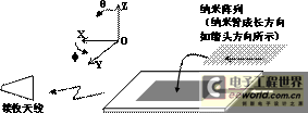
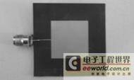
In order to verify the radiation performance of the carbon nanotube antenna array, we designed an experimental device as shown in Figure 3. The patch antenna in the figure is a Ku-band microstrip rectangular patch antenna, which serves as a feed source for spatial feeding of the carbon nanotube array. The actual picture is shown in Figure 4.

Figure 3 Schematic diagram of microstrip patch antenna experimental setup

Figure 4: Microstrip patch antenna
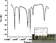
We loaded the nanotube array on the patch antenna, tested the standing wave and radiation pattern of the antenna, and compared them with the unloaded case to observe the radiation performance of the nanotube array. Figure 5 shows the S11 result tested by the HP8720ES vector network analyzer. It can be seen from the figure that there is no obvious change in S11 after loading the nanotube array. Figure 6 shows the test results of the normalized radiation pattern at several frequency points. The test plane is the yoz plane in Figure 3. From the test results, it can be found that after loading the nanotube array, the antenna radiation pattern has changed significantly, and a new lobe has appeared in the direction about 90 degrees away from the main radiation direction. Theoretical analysis shows that this is because the waveguide direction of the loaded nanotube array is perpendicular to the zenith direction of the patch antenna, and part of the energy coupled through the microstrip patch antenna space is guided by the nanotube array and radiated in the horizontal direction.

Figure 5 Test results of microstrip patch antenna S11


(a) (b)


(c) (d)


(e) (f)
Figure 6 Microstrip patch antenna radiation pattern test results
(a)13GHz, (b)13.1GHz, (c)13.2GHz, (d)13.3GHz, (e)13.4GHz,(f)13.5GHz
4.2 Experiment of loading nanotube array with microstrip Yagi antenna
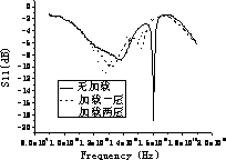
我们还设计了一种微带八木天线作为碳纳米管阵列空间馈电的馈源,采用的实验装置与天线实物图如图6, 7所示。这种微带天线具有较好的定向性,并且增加引向振子的数目能够显著提升它的定向能力,因此我们将纳米阵列贴在天线的引向振子处,并使纳米管线的方向与引向振子方向一致,测试结果如图8, 9所示。从图8可以看到,加载纳米阵列后天线的谐振频率发生了变化,这与矩形贴片天线的测试结果不同。另外,从方向图测试结果可以发现加载纳米阵列后天线定向性有所提高,理论分析表明是因为纳米管阵列增强了引向振子对能量的导引。

Figure 6 Schematic diagram of microstrip Yagi antenna experimental setup


(a) No loading (b) Loaded carbon nanotube array
Figure 7: Microstrip Yagi antenna

Figure 8 Microstrip Yagi antenna S11 test results


(a) (b)


(c) (d)
Figure 9 Microstrip Yagi antenna radiation pattern test results
(a)16GHz, (b)16.1GHz, (c)16.2GHz, (d)16.3GHz,
5 Conclusion
本文通过采用在微带天线上加载碳纳米管阵列的方法对碳纳米管阵列天线的辐射性能做了实验研究。文章首先测试和比较了两种微带天线加载碳纳米管阵列后辐射方向图的变化,其结果表明碳纳米管阵列能够显著改变天线的辐射特性。
References
- S. Iijima, Helical microtabules of graphitic carbon, Nature, vol. 354, pp. 56–58, 1991.
- Zhu Q, Wang R, Research on the possibility of nano-tube antenna, IEEE Antennas and Propagation Society International Symposium, 2004.
- Zhu Qi, Chen Chang, Ding Wenwu, Lu Jiaguo. The feasibility of developing nanotube array antennas using nanotechnology. Chinese Journal of Electronics, 2005, 33(9):1698-1701.
- M. Anantram and F. Leonard, Physics of carbon nanotube electronic devices, Reports Progr. Phys., vol. 69, pp. 507–561, Feb. 2006.
- M. S. Dresselhaus, G. Dresselhaus, and P. C. Eklund, Science of Fullerenes and Carbon Nanotubes. New York: Academic Press, 1996.
- G. Hanson, Fundamental transmitting properties of carbon nanotube antennas, IEEE Trans. Antennas Propag. 2005.
- Ying Lan, Baoqing Zeng, Hai Zhang, Beiran Chen and Zhonghai Yang, Simulation of carbon nanotube THz antenna arrays, International Journal of Infrared and Millimeter Waves, 2006.
- Yi Huang, Wenyan Yin and Qinghuo Liu, Performance Prediction of Carbon Nanotube Bundle Dipole Antennas, IEEE Trans on Nanotechnology, 2008.
- K. Kaneto, M. Tsuruta, G. Sakai, W. Y. Cho and Y. Ando, Electrical conductivities of multi-wall carbon nano tubes, Synthetic Metals, 1999.
- Qiu Linhai, Zhu Qi and Kuang Zeling, Investigation on wave-guiding properties of nanotube array, IEEE Antenna and Propagation Society International Symposium, 2009.
Previous article:0.2% accuracy dual-phase electricity meter solution
Next article:AMETEK Sorensen Solutions for Laser Diode Testing
- Keysight Technologies Helps Samsung Electronics Successfully Validate FiRa® 2.0 Safe Distance Measurement Test Case
- From probes to power supplies, Tektronix is leading the way in comprehensive innovation in power electronics testing
- Seizing the Opportunities in the Chinese Application Market: NI's Challenges and Answers
- Tektronix Launches Breakthrough Power Measurement Tools to Accelerate Innovation as Global Electrification Accelerates
- Not all oscilloscopes are created equal: Why ADCs and low noise floor matter
- Enable TekHSI high-speed interface function to accelerate the remote transmission of waveform data
- How to measure the quality of soft start thyristor
- How to use a multimeter to judge whether a soft starter is good or bad
- What are the advantages and disadvantages of non-contact temperature sensors?
- Innolux's intelligent steer-by-wire solution makes cars smarter and safer
- 8051 MCU - Parity Check
- How to efficiently balance the sensitivity of tactile sensing interfaces
- What should I do if the servo motor shakes? What causes the servo motor to shake quickly?
- 【Brushless Motor】Analysis of three-phase BLDC motor and sharing of two popular development boards
- Midea Industrial Technology's subsidiaries Clou Electronics and Hekang New Energy jointly appeared at the Munich Battery Energy Storage Exhibition and Solar Energy Exhibition
- Guoxin Sichen | Application of ferroelectric memory PB85RS2MC in power battery management, with a capacity of 2M
- Analysis of common faults of frequency converter
- In a head-on competition with Qualcomm, what kind of cockpit products has Intel come up with?
- Dalian Rongke's all-vanadium liquid flow battery energy storage equipment industrialization project has entered the sprint stage before production
- Allegro MicroSystems Introduces Advanced Magnetic and Inductive Position Sensing Solutions at Electronica 2024
- Car key in the left hand, liveness detection radar in the right hand, UWB is imperative for cars!
- After a decade of rapid development, domestic CIS has entered the market
- Aegis Dagger Battery + Thor EM-i Super Hybrid, Geely New Energy has thrown out two "king bombs"
- A brief discussion on functional safety - fault, error, and failure
- In the smart car 2.0 cycle, these core industry chains are facing major opportunities!
- The United States and Japan are developing new batteries. CATL faces challenges? How should China's new energy battery industry respond?
- Murata launches high-precision 6-axis inertial sensor for automobiles
- Ford patents pre-charge alarm to help save costs and respond to emergencies
- New real-time microcontroller system from Texas Instruments enables smarter processing in automotive and industrial applications
- Please restore the number of invitees to 8. Thank you. Thank you. I invited 8 people before, but there are already 6 people in the list.
- SensorTile.Box Expert Mode Gyroscope Sensor
- Why is the single-ended impedance on the PCB controlled to 50 ohms?
- Experts talk about IPC7351
- CC1101 Study Notes - Preliminary Understanding
- 5G commercial use is on the way, are you ready?
- Chat with Vicor engineers about efficient power supply and learn about modular power solutions for drones!
- Download the practical guide - Motor Control Basics
- DDR4 signal reference power layer, will the impedance have any impact?
- Questions about adjustable color temperature LED lamp circuit

 Signal feedback applications in low-field NMR and MRI


 京公网安备 11010802033920号