Electromagnetic flowmeter (EMF for short) is an instrument that uses Faraday's law of electromagnetic induction to measure the volume flow of conductive liquids . EMF was industrialized in the early 1950s. In recent years, EMF production accounts for about 5% to 6.5% of the total number of industrial flow meters worldwide . Especially since 2000, this value has been increasing year by year. As a type of industrial flow measurement instrument, electromagnetic flowmeter has some tips and precautions in its installation and use. Here I will discuss with you based on some of my personal experience, hoping to contribute to the correct installation and use of electromagnetic flowmeter.
2. Advantages of using magnetic flowmeter
The measuring channel of the electromagnetic flowmeter is a smooth straight tube without flow-blocking detection parts. It is not easy to be blocked and is suitable for measuring liquid-solid two-phase fluids containing solid particles or fibers, such as pulp, coal-water slurry, ore slurry, mud and sewage.
It does not generate pressure loss due to flow detection. The resistance of the instrument is only the resistance along the same length of the pipeline. The energy-saving effect is significant. It is most suitable for large-diameter water supply pipelines that require low resistance loss.
The volume flow rate measured by the electromagnetic flowmeter is actually not significantly affected by changes in fluid density, viscosity, temperature, pressure and conductivity (as long as it is above a certain threshold);
Compared with most other flow meters, it has lower requirements for the front straight pipe section;
The electromagnetic flowmeter has a large measurement range, usually 20:1 to 50:1, and a wide range of optional flow rates. The full-scale liquid velocity can be selected within 0.5 to 10 m/s. Some models of meters can expand and reduce the flow rate on site as needed (for example, a 4-digit potentiometer is provided to set the meter constant) without having to be removed for offline real-flow calibration;
The caliber range of electromagnetic flowmeter is wider than other types of flowmeters, ranging from a few millimeters to 3 meters; it can measure forward and reverse bidirectional flow, and can also measure pulsating flow, as long as the pulsating frequency is much lower than the excitation frequency; the meter output is essentially linear;
It is easy to select the material variety of the parts in contact with the fluid, and can be applied to corrosive fluids.
Of course, electromagnetic flowmeters also have disadvantages. For example, they cannot measure liquids with very low conductivity, such as petroleum products and organic solvents; they cannot measure gases, steam, and liquids containing many large bubbles; general-purpose EMF cannot be used to measure liquids at higher temperatures due to the limitations of lining materials and electrical insulation materials.
3. Precautions for installation and use
3.1 General matters needing attention during use
The liquid should have the conductivity required for measurement, and the conductivity distribution should be roughly uniform. Therefore, the flow sensor should be installed away from places where uneven conductivity is likely to occur, such as adding liquid near its upstream, and the liquid adding point is preferably located downstream of the sensor. When in use, the sensor measuring tube must be filled with liquid (except for non-full tube types). When the liquid is mixed, its distribution should be roughly uniform. The liquid should be at the same potential as the ground and must be grounded. For example, when the process pipeline is made of insulating materials such as plastic, the conveying liquid generates friction static electricity and other reasons, resulting in a potential difference between the liquid and the ground.
3.2 Flow sensor installation
3.2.1 Installation location
Usually, the protection level of the electromagnetic flow sensor shell is IP65 (dust and water spray level specified in GB 4208), and the following requirements are imposed on the installation site:
1) When measuring mixed phase fluids, choose a location that will not cause phase separation; when measuring two-component liquids, avoid installing it downstream where the mixture is not yet uniform; when measuring chemical reaction pipelines, install it downstream of the reaction section where the reaction is fully completed;
2) Avoid negative pressure in the measuring tube as much as possible;
3) Choose a location with little vibration, especially for integrated instruments ;
4) Avoid large motors, large transformers, etc. nearby to avoid electromagnetic interference;
5) A place where it is easy to achieve separate grounding of the sensor;
6) Avoid high concentration of corrosive gases in the surrounding environment as much as possible;
7) The ambient temperature is within the range of -25/-10 to 50/600℃. The temperature of the integrated structure is also subject to the electronic components, so the range is narrower.
8) The relative humidity of the environment is within the range of 10% to 90%;
9) Avoid direct sunlight as much as possible;
10) Avoid rain and will not be submerged in water.
If the protection level is IP67 (dust-proof and water-proof) or IP68 (dust-proof and submersible), the above requirements 8) and 10) are not required.
3.2.2 Straight pipe length requirements
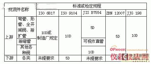
In order to obtain normal measurement accuracy, there must be a certain length of straight pipe section upstream of the electromagnetic flow sensor, but its length requirement is lower than that of most other flow meters . After the 90o elbow, T-shaped pipe, concentric reducer, and fully open gate valve, it is generally believed that as long as the straight pipe section is 5 times the diameter (5D) of the electrode center line (not the sensor inlet connection surface), valves with different openings require 10D; the downstream straight pipe section is (2~3)D or no requirement; but the butterfly valve disc must be prevented from extending into the sensor measuring tube. The upstream and downstream straight pipe section lengths proposed by various standards or verification procedures are also inconsistent, as shown in Table 1. The requirements are higher than the usual requirements. This is to ensure that the requirements of the current 0.5-level accuracy instrument are met.

If the valve can be opened for use, it should be installed at an angle of 45o between the valve cutoff direction and the electrode axis, so that the additional error can be greatly reduced.
3.2.3 Installation location and flow direction
The sensor can be installed horizontally, vertically or tilted without restriction. However, it is best to install it vertically when measuring solid-liquid two-phase fluids, flowing from bottom to top. This can avoid the disadvantages of severe local wear of the lower half of the lining when installed horizontally, and solid phase precipitation at low flow rates. [page]
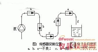
When installing horizontally, the electrode axis should be parallel to the horizon, not perpendicular to the horizon, because the electrode at the bottom is easily covered by sediments, and the top electrode is easily rubbed by bubbles in the liquid, covering the electrode surface, causing the output signal to fluctuate. In the pipe system shown in Figure 1, c and d are suitable positions; a, b, and e are unsuitable positions. The liquid may not be full at b, and gas may accumulate at a and e. The pipe section behind the sensor at e is short and may not be full. The discharge port is preferably as shown in shape f. For solid-liquid two-phase flow, c is also an unsuitable position.

3.2.4 Bypass pipe, easy-to-clean connections and pre-placed holes
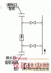
In order to facilitate the inspection and adjustment of the zero point when the process pipeline continues to flow and the sensor stops flowing, a bypass pipe should be installed. However, large-diameter pipe systems are often difficult to implement due to investment and location space limitations. It is difficult to correct the measured value according to the degree of electrode contamination, or to determine a contamination degree judgment standard that does not affect the measured value. In addition to the above, the use of non-contact electrodes or instruments with scraper cleaning devices can solve some problems. Sometimes it is also necessary to remove the inner wall attachments. In this case, it can be removed on the spot without removing the sensor as shown in Figure 2.

For pipes with a diameter greater than 1.5 to 1.6 m, pre-insert holes into the pipes near the EMF to facilitate cleaning of the inner wall of the sensor measuring tube when the pipe system stops running.
3.2.5 Installation of negative pressure piping system
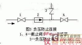
Fluoroplastic lined sensors must be used with caution in negative pressure piping systems; positive pressure piping systems should prevent negative pressure from being generated. For example, in piping systems where the liquid temperature is higher than room temperature, after the upstream and downstream stop valves of the sensor are closed and the operation is stopped, the fluid will cool and shrink to form negative pressure. A negative pressure prevention valve should be installed near the sensor, as shown in Figure 3. Some manufacturers stipulate that the absolute pressure of PTFE and PFA plastic linings used in negative pressure piping systems at 200C, 1000C, and 1300C must be greater than 27, 40, and 50KPa, respectively.

3.2.6 Grounding
The sensor must be grounded separately (grounding resistance below 100Ω). In principle, the grounding of the separated type should be on one side of the sensor, and the converter should be grounded at the same grounding point. If the sensor is installed on a pipeline with cathodic corrosion protection, in addition to grounding the sensor and the grounding ring together, a thicker copper wire (16mm2) should be used to bypass the sensor and connect the two connecting flanges of the pipeline to isolate the cathodic protection current from the sensor.
Sometimes the stray current is too large, such as the leakage current along the electrolyte of the electrolytic cell, which affects the normal EMF measurement . In this case, the flow sensor can be electrically isolated from the process to which it is connected. This method can also be used on pipelines with cathodic protection when the cathodic protection current affects the EMF measurement.
3.3 Converter installation and cable connection
The integrated EMF does not have a separate converter installed; the separate converter is installed near the sensor or in the instrument room, with a wider range of location options and better environmental conditions than the sensor. Its protection level is IP65 or IP64 (dust and splash proof). The requirements for the installation site are the same as those in 3.2.1, 3), 4), 6), 8), 9), and 10). The ambient temperature is limited by the electronic components, and the operating temperature range is narrower than that specified in 7).
The distance between the converter and the sensor is subject to the conductivity of the measured medium and the signal cable model, that is, the distributed capacitance of the cable, the conductor cross-section and the number of shielding layers. The signal cable provided by the manufacturer with the instrument (or the specified model) should be used. For liquids with low conductivity and long transmission distances, it is also specified to use three-layer shielded cables. The "instruction manual" of the general instrument gives the corresponding transmission distance range for liquids with different conductivity. Single-layer shielded cables are usually used for industrial water or acid and alkali solutions. The transmission distance is usually 100m.
To avoid signal interference, the signal cable must be installed separately in a grounded protective steel pipe. The signal cable and power line cannot be installed in the same steel pipe.
4. Conclusion
As enterprises move towards the market, their production and operation management will be further deepened, and flow measurement will become more important. As a kind of industrial flow measurement instrument, electromagnetic flowmeter should play its role. How to install and use it correctly on the basis of good selection has become a key issue. Therefore, automation instrument professionals, on the premise of having certain professional knowledge, need to master certain skills and methods on how to install and use it correctly. Only in this way can the requirements of enterprises be met and flow measurement can play an important role.
Previous article:Troubleshooting of pressure gauges and instruments
Next article:How to use a megohmmeter to measure insulation resistance correctly?
- New IsoVu™ Isolated Current Probes: Bringing a New Dimension to Current Measurements
- Modern manufacturing strategies drive continuous improvement in ICT online testing
- Methods for Correlation of Contact and Non-Contact Measurements
- Keysight Technologies Helps Samsung Electronics Successfully Validate FiRa® 2.0 Safe Distance Measurement Test Case
- From probes to power supplies, Tektronix is leading the way in comprehensive innovation in power electronics testing
- Seizing the Opportunities in the Chinese Application Market: NI's Challenges and Answers
- Tektronix Launches Breakthrough Power Measurement Tools to Accelerate Innovation as Global Electrification Accelerates
- Not all oscilloscopes are created equal: Why ADCs and low noise floor matter
- Enable TekHSI high-speed interface function to accelerate the remote transmission of waveform data
- Intel promotes AI with multi-dimensional efforts in technology, application, and ecology
- ChinaJoy Qualcomm Snapdragon Theme Pavilion takes you to experience the new changes in digital entertainment in the 5G era
- Infineon's latest generation IGBT technology platform enables precise control of speed and position
- Two test methods for LED lighting life
- Don't Let Lightning Induced Surges Scare You
- Application of brushless motor controller ML4425/4426
- Easy identification of LED power supply quality
- World's first integrated photovoltaic solar system completed in Israel
- Sliding window mean filter for avr microcontroller AD conversion
- What does call mean in the detailed explanation of ABB robot programming instructions?
- STMicroelectronics discloses its 2027-2028 financial model and path to achieve its 2030 goals
- 2024 China Automotive Charging and Battery Swapping Ecosystem Conference held in Taiyuan
- State-owned enterprises team up to invest in solid-state battery giant
- The evolution of electronic and electrical architecture is accelerating
- The first! National Automotive Chip Quality Inspection Center established
- BYD releases self-developed automotive chip using 4nm process, with a running score of up to 1.15 million
- GEODNET launches GEO-PULSE, a car GPS navigation device
- Should Chinese car companies develop their own high-computing chips?
- Infineon and Siemens combine embedded automotive software platform with microcontrollers to provide the necessary functions for next-generation SDVs
- Continental launches invisible biometric sensor display to monitor passengers' vital signs
- Data Acquisition (DAQ) Basics (Part 2)
- How to connect the freewheeling diode
- Design Techniques for Planar UWB Antennas for Communications
- Online programming tool SplootCode Editor
- Detailed explanation of ADC of MSP430 microcontroller
- Component packaging,
- Question about the placement of pull-up resistors
- 5 Key Considerations for IoT Devices
- This is a VHF/UHF book
- NUCLEO_G431RB Review Add UART

 A brief discussion on the application of non-collecting electromagnetic flowmeter in polymer stratification test


 京公网安备 11010802033920号