1. Introduction
In the intermediate test of quartz crystal, it is necessary to measure parameters such as series resonant frequency, series resonant resistance, load resonant frequency, load resonant resistance, static capacitance, dynamic capacitance, frequency pulling sensitivity and DLD. Among them, static capacitance C0 is mainly determined by the silver film on both ends of the quartz crystal, which characterizes the static characteristics of the quartz crystal and is closely related to application indicators such as the series resonant frequency and load resonant frequency of the quartz crystal.
At present, the standard method for measuring quartz crystals recommended by IEC (International Electrotechnical Commission) is the π network zero phase method. In this method, the standard method for measuring static capacitance is not specified. If common methods such as the resonance method and the AC bridge method are used to measure static capacitance, the complexity of the entire measurement system will increase and the measurement of the resonant frequency will be adversely affected. This project proposes a new method for measuring the static capacitance of quartz crystals based on the π network zero phase method, and designs and manufactures an experimental measurement system based on this method.
2. Measurement principle and circuit
2.1 Equivalent electrical parameter model of quartz crystal
The equivalent electrical parameter model of a quartz crystal is shown in Figure 1:
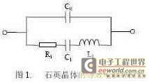
Among them, C0 is the capacitance between the two electrodes of the quartz crystal, which is called the static capacitance of the quartz crystal, C1 is called the dynamic capacitance of the quartz crystal, L1 is called the dynamic inductance of the quartz crystal, and R1 represents the loss of the quartz crystal during vibration, which is called the series resonant resistance. When the frequency of the excitation signal is equal to the resonant frequency of the quartz crystal, its equivalent electrical parameter model is a pure resistor. Since the values of C1 and L1 are very small, when the frequency of the excitation signal is far away from the resonant frequency of the quartz crystal, the influence of R1, C1, and L1 can be ignored. At this time, the quartz crystal is equivalent to a capacitor with a value of C0.
2.2 Principle of π network method
The π network recommended by IEC is shown in Figure 2:
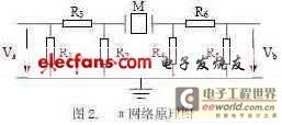
The impedance of the network matches the impedance of the test instrument and attenuates the reflected signal from the test instrument. M is the quartz crystal to be tested. Va is the input excitation signal, and Vb is the π network output signal, both of which are vector voltage signals. When the quartz crystal is in a resonant state, it exhibits a pure resistance characteristic. At this time, the phase difference between Va and Vb is zero, and the frequency of Va is the series resonant frequency of the quartz crystal. Therefore, the resonant frequency of the quartz crystal can be found by changing the frequency of Va and detecting the phase difference between Va and Vb. IEC has not recommended a standard method for measuring the static capacitance of quartz crystals in a π network. The pπ network consists of a symmetrical double π-type resistor loop. R1, R2 and R3 constitute the input attenuator, and R4, R5 and R6 constitute the output attenuator. Their function is to make
2.3 Commonly used methods for measuring capacitance
Commonly used methods for measuring capacitance include the resonance method, the AC bridge method, and the charge-discharge method. The resonance method introduces capacitance into the oscillation circuit so that the oscillation frequency becomes a function of the capacitance, and the capacitance value is calculated by measuring the frequency value. The AC bridge method connects the capacitance to the AC bridge, adjusts the adjustable resistance and adjustable capacitance in the bridge to balance the bridge, and calculates the measured capacitance value based on the resistance and capacitance values of each arm of the bridge when balanced. The charge-discharge method uses an AC signal source to charge the capacitor, and then connects the capacitor to the discharge circuit, and calculates the capacitance value by measuring the discharge time of the capacitor. Since the π network method obtains the electrical parameter value of the quartz crystal by measuring the vector voltage at both ends of the π network, it is inconsistent with the above three methods. Therefore, if these three methods are used to measure the static capacitance of the quartz crystal, additional measurement circuits need to be added, and the stray terms of the π network circuit will be increased, which will have an adverse effect on the measurement of the resonant frequency of the quartz crystal.
2.4 Electrostatic capacitance measurement method based on π network
Using a DDS (direct digital frequency synthesis) signal source as an excitation source, the frequency of its output AC signal is far away from the resonant frequency of the quartz crystal. This signal excites the π network connected to the quartz crystal to be measured. At this time, the quartz crystal is equivalent to a capacitor with a value of C0. There is a certain functional relationship between the output voltage of the π network and the capacitor. Since the input voltage and the parameters of the π network are known, the output voltage can be measured and the C0 value can be calculated based on this functional relationship. This method is very similar to the method of measuring the resonant frequency of a quartz crystal. Both require using the DDS output signal as an excitation signal and detecting the vector voltage output by the π network. The difference between the two is that measuring the resonant frequency requires detecting the phase difference between the input voltage and the output voltage, while measuring the static capacitance requires measuring the amplitude of the input voltage and the output voltage. Therefore, using the amplitude and phase detection method for these two vector voltage signals can unify the measurement of the resonant frequency and static capacitance of the quartz crystal.
The principle block diagram is shown in Figure 3:
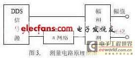
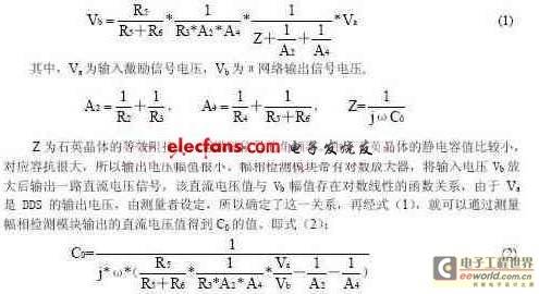
Among them, DDS outputs two signals with the same amplitude, frequency and phase. One channel excites the π network, and the other channel inputs the amplitude and phase detection module. This project requires that the measurement range of the quartz crystal resonant frequency is 0-200MHz. Within this range, two frequency points of 30MHz and 68MHz are selected as the set frequencies of the excitation signal. The specific method is that when the resonant frequency of the quartz crystal is around 30MHz, the DDS output signal frequency is set to 68MHz, otherwise, it is set to 30MHz. After the excitation signal passes through the π network, the output voltage is as follows:
 [page]
3. Test system design
3.1 Test system hardware design
The hardware block diagram of the test system is shown in Figure 4:

The test system hardware consists of a computer, a CPLD chip, a DDS signal source, a π network, an amplitude phase detection module, and an A/D converter. Among them, the CPLD, DDS, the amplitude phase detection module, and the A/D converter are integrated on a PCI expansion board. The address and data signals sent by the computer as the control core through the PCI interface are converted by the CPLD chip into corresponding control logic to control the operation of the DDS, the amplitude phase detection module, and the A/D converter. The DDS signal source sends a signal of set frequency, phase, and amplitude to excite the π network. The π network has a socket, which can be inserted into crystals or components such as resistors and capacitors. The vector voltage signal Vb output by the π network is connected to the amplitude phase detection module. The output DC voltage of the amplitude phase detection module is input into the A/D converter, and after being converted into a digital signal, it is input into the computer through the CPLD.
3.2 Test system software design
The test software is written in Visual C++ language to realize the functions of human-computer interaction interface, measurement control and data processing. The measurement control includes the setting of the frequency, phase and amplitude control words of each channel of DDS, as well as the writing of the internal instruction register of the A/D converter and the reading of the conversion results. The data processing part mainly calculates the output DC voltage of the amplitude and phase detection module that has been converted into a digital quantity, and obtains the value of the static capacitance from the above relationship. Because under actual measurement conditions, there is not a strict logarithmic linear relationship between the DC voltage and Vb, it is necessary to fit this functional relationship. According to the fitted relationship, Vb can be calculated from the DC voltage value, and then the value of the static capacitance C0 can be obtained according to the equation listed above.
4. Experimental data and processing
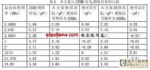
Using S&A's 250B as a standard instrument, the C0 value measured by this solution is compared with the measurement result of 250B to check whether the measurement accuracy meets the requirements of industrial production. In industrial production, the measurement range of quartz crystal static capacitance is required to be 1-10pF, and the measurement error is less than 0.1pF. The experimental data is shown in Table 1:
5. Conclusion
Based on the π network zero phase method, the static capacitance of the quartz crystal is measured by the method of "DDS excitation, π network response, amplitude phase detection and calculation of capacitive reactance", and an experimental measurement system is designed and manufactured to implement the scheme. This method unifies the measurement of the static capacitance and resonant frequency of the quartz crystal and simplifies the measurement circuit. Through the actual measurement of a batch of crystals and small capacitors, it is proved that the measurement error is less than 0.1pF in the range of 1 to 10pF, which can meet the actual requirements. On this basis, an actual quartz crystal intermediate test system can be developed.
Previous article:Software-calibrated 50 MHz to 9 GHz RF power measurement system
Next article:Simulation analysis of impedance characteristics of resistors, inductors and capacitors
- Popular Resources
- Popular amplifiers
-
 Investigation of occupancy perception in autonomous driving: An information fusion perspective
 -
 Practical Development of Automotive FlexRay Bus System (Written by Wu Baoxin, Guo Yonghong, Cao Yi, Zhao Dongyang, etc.)
 -
 Deep Learning Computer Vision: Neural Network Architectures Using Python and Keras
 -
 PyTorch Deep Learning
- Keysight Technologies Helps Samsung Electronics Successfully Validate FiRa® 2.0 Safe Distance Measurement Test Case
- From probes to power supplies, Tektronix is leading the way in comprehensive innovation in power electronics testing
- Seizing the Opportunities in the Chinese Application Market: NI's Challenges and Answers
- Tektronix Launches Breakthrough Power Measurement Tools to Accelerate Innovation as Global Electrification Accelerates
- Not all oscilloscopes are created equal: Why ADCs and low noise floor matter
- Enable TekHSI high-speed interface function to accelerate the remote transmission of waveform data
- How to measure the quality of soft start thyristor
- How to use a multimeter to judge whether a soft starter is good or bad
- What are the advantages and disadvantages of non-contact temperature sensors?
- Innolux's intelligent steer-by-wire solution makes cars smarter and safer
- 8051 MCU - Parity Check
- How to efficiently balance the sensitivity of tactile sensing interfaces
- What should I do if the servo motor shakes? What causes the servo motor to shake quickly?
- 【Brushless Motor】Analysis of three-phase BLDC motor and sharing of two popular development boards
- Midea Industrial Technology's subsidiaries Clou Electronics and Hekang New Energy jointly appeared at the Munich Battery Energy Storage Exhibition and Solar Energy Exhibition
- Guoxin Sichen | Application of ferroelectric memory PB85RS2MC in power battery management, with a capacity of 2M
- Analysis of common faults of frequency converter
- In a head-on competition with Qualcomm, what kind of cockpit products has Intel come up with?
- Dalian Rongke's all-vanadium liquid flow battery energy storage equipment industrialization project has entered the sprint stage before production
- Allegro MicroSystems Introduces Advanced Magnetic and Inductive Position Sensing Solutions at Electronica 2024
- Car key in the left hand, liveness detection radar in the right hand, UWB is imperative for cars!
- After a decade of rapid development, domestic CIS has entered the market
- Aegis Dagger Battery + Thor EM-i Super Hybrid, Geely New Energy has thrown out two "king bombs"
- A brief discussion on functional safety - fault, error, and failure
- In the smart car 2.0 cycle, these core industry chains are facing major opportunities!
- The United States and Japan are developing new batteries. CATL faces challenges? How should China's new energy battery industry respond?
- Murata launches high-precision 6-axis inertial sensor for automobiles
- Ford patents pre-charge alarm to help save costs and respond to emergencies
- New real-time microcontroller system from Texas Instruments enables smarter processing in automotive and industrial applications
- Using IQmat in TMS320F28x7x
- Definition of various data types in TI DSP
- TI eSports training video recommendation
- Permanent magnet brushless motor and its driving technology
- Using cartridges and the ESP8266 microcontroller, a master gave Game Boy the ability to surf the Internet
- A way to significantly improve the distortion of audio playback systems
- MSP430F149
- It is time to accumulate some knowledge on GaN power device design when developing switching power supplies
- Brief Introduction to the Principle and Design of Flyback Converter
- WIFI development software tool sharing

 Investigation of occupancy perception in autonomous driving: An information fusion perspective


 京公网安备 11010802033920号