1 System hardware design
1.1 Selection of inertial measurement devices
According to the characteristics of motion trajectory tracking and the characteristics of the experiment itself, the micro-inertial measurement device should meet the following design requirements: small size, light weight, low power consumption, high acquisition frequency and acquisition accuracy, low cost and strong impact resistance. In order to achieve these requirements, the hardware of the micro-inertial measurement device is mainly composed of micro-inertial sensor unit MEMS and microprocessor unit DSP. The micro-inertial sensor unit consists of a micro-mechanical gyroscope and a micro-accelerometer, which can accurately measure the three-axis angular velocity information and three-axis acceleration information of the carrier. Accelerometers
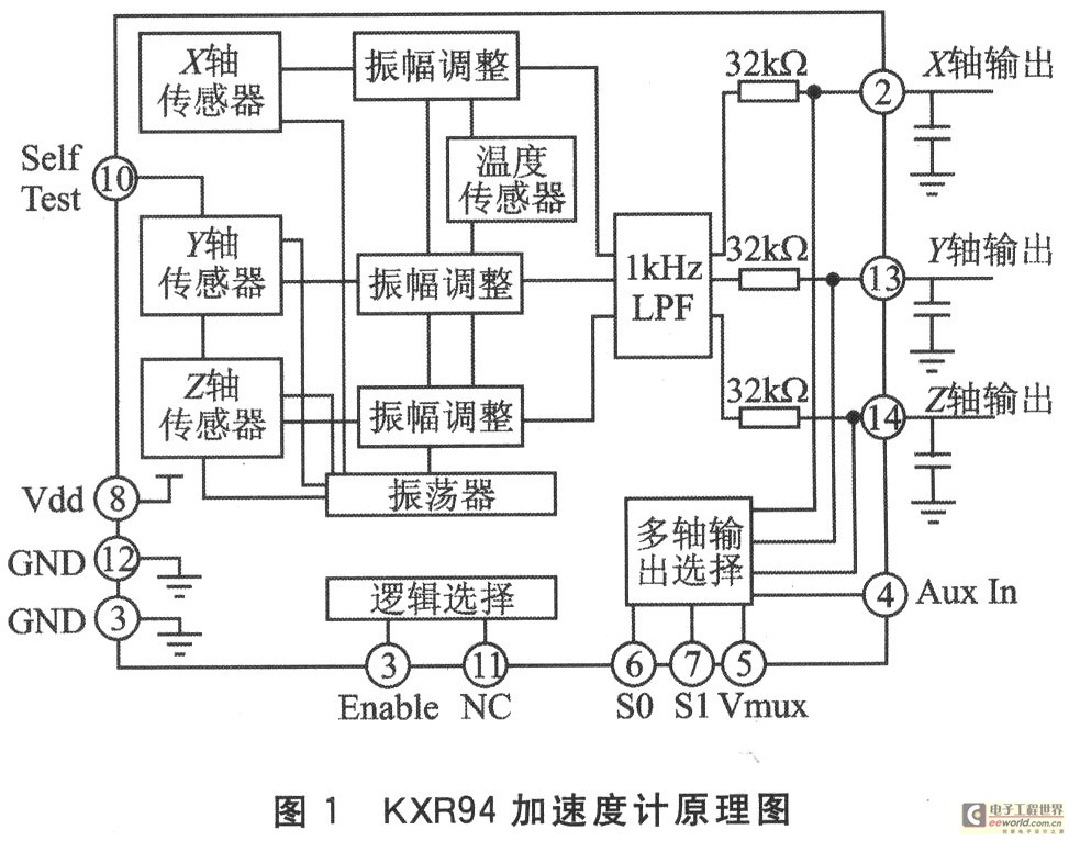
are an important type of sensitive element in inertial navigation and inertial guidance systems. They are used to measure the acceleration of the carrier relative to the inertial space. After integration and related operations, the position of the carrier space can be obtained. The accelerometer is a direct measurement element that can continuously measure the acceleration of the carrier, and then calculate the carrier speed, longitude and latitude, and range through a computer. The KXR94 accelerometer chip used in this system is a three-axis accelerometer produced by Kionix. The accelerometer has been designed to compensate for the deviation caused by temperature and voltage fluctuations, so the deviation caused by voltage and temperature is small. The device has a measurement range of ±2 g, a sensitivity coefficient of 560 mV/g, a nonlinearity of 0.1%, and a zero acceleration drift of ±150 mg; it can work at 2.8 to 3.3 V; the power consumption is very low, and the static current is about 1.1 mA. Its schematic diagram is shown in Figure 1.

[page]
The gyroscope is used to measure the angular velocity of the carrier. In this design, the IDG-300 dual-axis gyroscope produced by InvenSense is used. It takes 200 ms for its accuracy to stabilize within ±3°/s. The device is powered by 3.0~3.3 V; the range of measuring yaw angular velocity is ±500°/s, the sensitivity is 2 mV/(rad·s-1), and the zero output voltage is 1.5 V; the range, bandwidth and zero output voltage of the angular velocity can be set by external resistors and capacitors. Its schematic diagram is shown in Figure 2.

This gyro does not compensate for the fluctuations caused by internal temperature and voltage, which should be fully considered in the design. The shortcomings can be compensated from two aspects: ① When designing the circuit board layout, the gyro and accelerometer chips should be kept as far away as possible from the power supply, serial port and other chips on the circuit board that generate heat and have large voltage fluctuations; ② When designing the software algorithm, the temperature drift coefficient of the gyro should be used to correct it.
1.2 Hardware circuit design
The DSP uses the C2000 series 32-bit fixed-point signal processor TMS320F2812 released by TI. It integrates a high-performance DSP core, 128 KB on-chip Flash memory, 16-channel 12-bit A/D converter and SCI serial communication interface. The analog quantity measured by the sensor unit is collected and written into the on-chip Flash by the A/D converter integrated on the DSP chip. All information is processed by the DSP's strapdown inertial navigation to obtain the position information of the measured target. The final result is sent directly to the host computer through RS232 and displayed and output.
Two IDG-300 gyroscopes are used in the construction of the system, and the angle measurement of one axis can be used as a redundant design. Because the algorithm requires that the acquisition of accelerometer and gyroscope analog signals be strictly controlled at the same time, two AD684 sample-and-hold amplifiers are selected. Each sampling channel of AD684 can complete sampling within 1μs, and the signal loss rate is no more than 0.01 μV/μs, and it has good linearity and AC characteristics. The control signal of AD684 is S/Hn. Pulling this pin low will perform sampling and holding. The system connects the S/Hn signals of two AD684 to an I/O pin of DSP, so that all collected signals can be sampled and held to prepare for DSP acquisition. Figure 3 is the hardware connection diagram of the inertial measurement device. The DSP peripheral part is powered by 3.3 V, so the signal characteristics of its SCI pin are TTL level. In actual use, it is usually necessary to convert the TTL level to RS232 level. MAX3232 is selected in the system to convert the SCI interface signal of DSP into the RS232 signal of the computer for communication. This is because the working range of RS232 is -15 to +15 V. Even if there is voltage attenuation in such a wide range, the transmission signal can be reliably identified; and in general, the longer the transmission line, the more serious the attenuation. Therefore, under the same conditions, RS232 is more capable of long-distance transmission. In order to enable the device to achieve long-distance transmission, and considering the versatility of the RS232 interface, this system chooses MAX3232 for communication with the host computer.

2 System software design
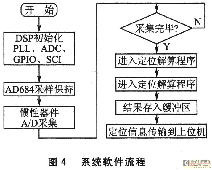
The inertial navigation system is a dead reckoning navigation method, that is, according to the continuously measured heading angle and velocity of the carrier, the position of the next point is deduced from the position of a known point, so that the current position of the moving body can be continuously measured. The gyroscope in the inertial navigation system is used to form a navigation coordinate system, so that the measuring axis of the accelerometer is stable in the coordinate system, and the heading and attitude angle are given; the accelerometer is used to measure the acceleration of the moving body, and the velocity is obtained by integrating the time once, and the distance is obtained by integrating the time once again. Therefore, based on the measurement of the carrier's angular velocity and acceleration information, the device can determine the position of the carrier and the parameters of the earth's gravity field, thereby realizing the measurement of various motion state information of the carrier. After the DSP is reset, this system first initializes the chip, configures various functional modules such as PLL, ADC, GPIO, SCI, and then configures peripherals such as AD684; when AD684 completes the signal acquisition of the accelerometer and gyroscope, it enters the positioning solution program and stores the results in the buffer; finally, the positioning information is output to the host computer. The system software flow is shown in Figure 4.

[page]
3 Experimental results
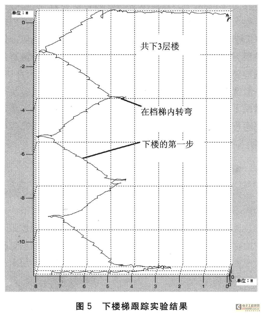
Under laboratory conditions, the micro-inertial measurement device was tied to the legs of a person, and tracking experiments were carried out on the person walking down the stairs and walking around a circular corridor. The experimental results show that the device can correctly track every step of the person under test, and the effect is good. Figures 5 and 6 show the movement trajectory of the person under test output by the device in two cases.


4 Conclusion
This system consists of a TMS320F2812 signal processor, an IDG-300 gyroscope, and a KXR94 accelerometer to form a miniature inertial measurement device. The device can accurately track moving targets and has the advantages of small size, light weight, low power consumption, and low cost. Given the characteristics of the device, it can also be applied to mobile phones with motion detection and state perception to monitor the location and usage of the mobile phone; laptops and media players with hard disk protection systems; mobile game consoles that provide more interactive, intuitive, and interesting gaming experiences by improving current game interfaces and developing new motion-based games; digital cameras that automatically help users take better photos by detecting position, motion, and vibration, etc.
Previous article:Embedded test solutions and high-speed test technology
Next article:Design of high-precision multi-channel temperature measurement system based on SPCE061A
- Popular Resources
- Popular amplifiers
- Keysight Technologies Helps Samsung Electronics Successfully Validate FiRa® 2.0 Safe Distance Measurement Test Case
- From probes to power supplies, Tektronix is leading the way in comprehensive innovation in power electronics testing
- Seizing the Opportunities in the Chinese Application Market: NI's Challenges and Answers
- Tektronix Launches Breakthrough Power Measurement Tools to Accelerate Innovation as Global Electrification Accelerates
- Not all oscilloscopes are created equal: Why ADCs and low noise floor matter
- Enable TekHSI high-speed interface function to accelerate the remote transmission of waveform data
- How to measure the quality of soft start thyristor
- How to use a multimeter to judge whether a soft starter is good or bad
- What are the advantages and disadvantages of non-contact temperature sensors?
- Innolux's intelligent steer-by-wire solution makes cars smarter and safer
- 8051 MCU - Parity Check
- How to efficiently balance the sensitivity of tactile sensing interfaces
- What should I do if the servo motor shakes? What causes the servo motor to shake quickly?
- 【Brushless Motor】Analysis of three-phase BLDC motor and sharing of two popular development boards
- Midea Industrial Technology's subsidiaries Clou Electronics and Hekang New Energy jointly appeared at the Munich Battery Energy Storage Exhibition and Solar Energy Exhibition
- Guoxin Sichen | Application of ferroelectric memory PB85RS2MC in power battery management, with a capacity of 2M
- Analysis of common faults of frequency converter
- In a head-on competition with Qualcomm, what kind of cockpit products has Intel come up with?
- Dalian Rongke's all-vanadium liquid flow battery energy storage equipment industrialization project has entered the sprint stage before production
- Allegro MicroSystems Introduces Advanced Magnetic and Inductive Position Sensing Solutions at Electronica 2024
- Car key in the left hand, liveness detection radar in the right hand, UWB is imperative for cars!
- After a decade of rapid development, domestic CIS has entered the market
- Aegis Dagger Battery + Thor EM-i Super Hybrid, Geely New Energy has thrown out two "king bombs"
- A brief discussion on functional safety - fault, error, and failure
- In the smart car 2.0 cycle, these core industry chains are facing major opportunities!
- The United States and Japan are developing new batteries. CATL faces challenges? How should China's new energy battery industry respond?
- Murata launches high-precision 6-axis inertial sensor for automobiles
- Ford patents pre-charge alarm to help save costs and respond to emergencies
- New real-time microcontroller system from Texas Instruments enables smarter processing in automotive and industrial applications
- Iwatch Apple Watch Wireless Charging
- Practical sharing: A collection of 5G manuscripts by frontline engineers
- New Forum Homepage User Guide
- Please help me with some questions about using AD for beginners
- Ultimate Electronics
- EEWORLD University ----TI Automotive Instrument Solutions
- CC2541 Bluetooth Watchdog Mode
- How do companies control the departure of technical developers who hold core secrets (such as SLE4442 card passwords)?
- Bluetooth module interfaces
- Lost, lost, lost

 Design of MSINS/GPS Integrated Navigation Computer Based on DSP


 京公网安备 11010802033920号