1. Introduction
AC speed control systems usually use IGBT pulse width modulation drivers to control the execution motor to operate in four quadrants, thereby meeting the high precision and high real-time requirements of the control system. The driver is the core part of the AC speed control unit in the control system, and its quality and performance directly affect the accuracy and performance of the entire control system. However, during use, once the driver fails, it will affect the normal operation of the entire control system. Therefore, it is necessary to design and develop a driver comprehensive performance test system to quickly troubleshoot and ensure the performance quality of the control system.
2. Driver working principle and test system technical features

Figure 1: Schematic diagram of the drive speed control system
Drive speed regulation can generally be divided into four parts: rectification, DC holding, inversion and control. The current regulator compares and adjusts the actual current value with the given value. The speed regulator obtains the actual speed value through the speed measuring motor and rotor position detection, and adjusts the speed value.
The driver is a high-power precision device, which may interfere with the outside world and affect normal operation. The noise signals generated by other devices on the same power supply may also enter the driver through radiation and power conduction. At the same time, the high-order harmonics and radio noise generated by the driver are also likely to affect the power grid and surrounding equipment. Eliminating interference and making the equipment work normally is a major feature of this system, but also a difficulty. The design adopts a standard grounding method, and connects a filter device to the front and rear ends of the driver. The surge current limiting circuit is connected in series in the circuit to effectively avoid mutual interference and make each test signal accurate and reliable.
The test system adopts two test methods: online or offline. The software realizes the function of intelligent processing module and the expert system provides solutions for test problems.
3. Hardware circuit implementation of driver test system
The test system mainly includes a test control station with a computer as the core and a test platform for installing the driver to be tested, simulated load, special measuring instruments and other equipment. The circuit design adopts pulse diagnosis anti-interference and redundant design to ensure that the hardware design is accurate and reliable. The specific connection diagram is as follows:
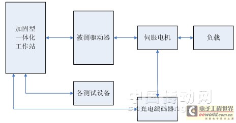
Figure 2: Driver test system connection diagram
3.1 Starting circuit
The startup circuit provides the working voltage for the driver under test. Three current limiting resistors are connected in series in the circuit to prevent surge current. At the same time, the contactor, thermal relay and filter ensure the quality of the voltage provided is stable and reliable. During the power-on process, it is only necessary to control the computer to issue a power-on command, the contactor will act, and the power-on process will be completed to achieve a safe and reliable "soft start". The schematic diagram of the startup circuit is shown below.
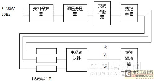
Figure 3: Schematic diagram of the startup circuit
3.2 Enabling and Detection Circuit
To ensure that the driver under test is in a controllable state, the pulse enable and drive enable of the driver under test are controlled through the software interface. At the same time, the enable status is displayed on the display interface to make the operation more intuitive.
The driver is powered on and enabled to communicate through the serial port, and the working status of the driver is detected in real time through the serial port. The serial port communication uses the communication card PCL745, which has strong anti-interference ability through differential input, and does not need to add 232 or 485 conversion modules, and can directly communicate with the ADAM module. The specific connection diagram is as follows.
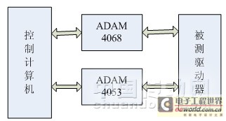
Figure 4: Connection diagram of enabling and detection modules [page]
4. Test system software features
The test system software is compiled according to the requirements of software engineering, striving to be powerful, stable and reliable. At the same time, the software is expanded to have expert system functions.
4.1 Human-computer interaction interface
The interface is the manifestation of the test system and a window for users to make analysis and judgment. Users can set self-check items and test items, and can also print and diagnose faults. The items to be tested are set in the human-computer interaction interface. The computer sends speed instructions to the drive under test. The test software performs online analysis and comparison of data obtained through the dedicated interface and other test equipment, and gives a conclusion on whether it is qualified or not. At the same time, the knowledge of the expert diagnosis knowledge base is called to perform fault diagnosis and provide solutions to the faults. The human-computer interaction interface module is shown in Figure 5.
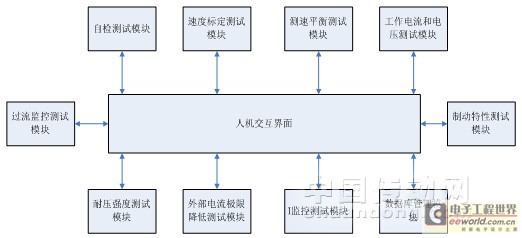
Figure 5: Human-computer interaction interface module diagram
4.2 Test system dynamic link library
The test system dynamic link library uses the standard access method ODBC (Open Database Connectivity) to establish a set of dynamic link libraries DLL, namely the basic information library of the driver and the special machine diagnosis knowledge base. The basic information library of the driver mainly contains the technical parameters of the driver, and the expert diagnosis knowledge base mainly analyzes the typical faults of the driver. If the user needs to expand the content of the expert diagnosis knowledge base, it can be added through the human-machine interface.
4.2 Important project testing
4.2.1 External current limit reduction test
When a -10V voltage is applied to the XX terminal of the driver under test, the overcurrent monitoring function of the speed controller loses its function. According to the current reduction characteristic curve, the maximum output current is limited to 40%I max . The speed setting value is set to -5V, the drive enable is turned on for 3 minutes and then turned off. The waveform of the detection hole is measured. The amplitude of I ist should be 4+0.4V, and the "overcurrent" indicator light is off. The current reduction characteristic curve is shown in Figure 6.
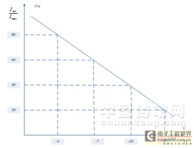
Figure 6: Current reduction characteristic curve
4.2.2I 2 t monitoring test
The I 2 t function approximates the square of the actual current value and integrates the result. If the actual current value is 1.1 times the rated value, the integrator integrates negatively, otherwise it integrates positively.
The specific test uses a test power board to replace the power module of the driver, closes the corresponding switch, and adds a -1V voltage to the XX terminal. From the XX characteristic curve, it can be seen that the maximum output current is 100%'I max . In this test interface, the speed setting is set to -5V, the drive is enabled, the W hole I ist waveform is measured, and the recorded data is input into the corresponding unit. The background software can give a qualified conclusion through calculation (the final trend of the I ist amplitude decrease should be 1.1I N , and the maximum amplitude holding time T should be ).
5. Conclusion
The drive test system can test the drive in both offline and online states. The test system can help the commissioning personnel quickly determine and understand the drive status during commissioning or use, and propose solutions. The operation is simple and fast, and the human-computer interaction is good. The system follows the principles of universalization, standardization and modularization design, and has good interactivity, portability and scalability. The design of this test system has been completed, which has greatly facilitated the maintenance of the drive. At the same time, the portable drive test system is also under research and design and will be completed soon.
Previous article:Application of A/D Converter ADS7822 in High-Speed Data Acquisition
Next article:High power DC motor test power supply design source
Recommended ReadingLatest update time:2024-11-16 20:44


- Popular Resources
- Popular amplifiers
-
 Siemens Motion Control Technology and Engineering Applications (Tongxue, edited by Wu Xiaojun)
 -
 Modern Product Design Guide
 -
 Modern arc welding power supply and its control
 -
 Small AC Servo Motor Control Circuit Design (by Masaru Ishijima; translated by Xue Liang and Zhu Jianjun, by Masaru Ishijima, Xue Liang, and Zhu Jianjun)
- Keysight Technologies Helps Samsung Electronics Successfully Validate FiRa® 2.0 Safe Distance Measurement Test Case
- From probes to power supplies, Tektronix is leading the way in comprehensive innovation in power electronics testing
- Seizing the Opportunities in the Chinese Application Market: NI's Challenges and Answers
- Tektronix Launches Breakthrough Power Measurement Tools to Accelerate Innovation as Global Electrification Accelerates
- Not all oscilloscopes are created equal: Why ADCs and low noise floor matter
- Enable TekHSI high-speed interface function to accelerate the remote transmission of waveform data
- How to measure the quality of soft start thyristor
- How to use a multimeter to judge whether a soft starter is good or bad
- What are the advantages and disadvantages of non-contact temperature sensors?
- Innolux's intelligent steer-by-wire solution makes cars smarter and safer
- 8051 MCU - Parity Check
- How to efficiently balance the sensitivity of tactile sensing interfaces
- What should I do if the servo motor shakes? What causes the servo motor to shake quickly?
- 【Brushless Motor】Analysis of three-phase BLDC motor and sharing of two popular development boards
- Midea Industrial Technology's subsidiaries Clou Electronics and Hekang New Energy jointly appeared at the Munich Battery Energy Storage Exhibition and Solar Energy Exhibition
- Guoxin Sichen | Application of ferroelectric memory PB85RS2MC in power battery management, with a capacity of 2M
- Analysis of common faults of frequency converter
- In a head-on competition with Qualcomm, what kind of cockpit products has Intel come up with?
- Dalian Rongke's all-vanadium liquid flow battery energy storage equipment industrialization project has entered the sprint stage before production
- Allegro MicroSystems Introduces Advanced Magnetic and Inductive Position Sensing Solutions at Electronica 2024
- Car key in the left hand, liveness detection radar in the right hand, UWB is imperative for cars!
- After a decade of rapid development, domestic CIS has entered the market
- Aegis Dagger Battery + Thor EM-i Super Hybrid, Geely New Energy has thrown out two "king bombs"
- A brief discussion on functional safety - fault, error, and failure
- In the smart car 2.0 cycle, these core industry chains are facing major opportunities!
- The United States and Japan are developing new batteries. CATL faces challenges? How should China's new energy battery industry respond?
- Murata launches high-precision 6-axis inertial sensor for automobiles
- Ford patents pre-charge alarm to help save costs and respond to emergencies
- New real-time microcontroller system from Texas Instruments enables smarter processing in automotive and industrial applications
- Industrial computer case
- EEWORLD University Hall----Live Replay: Datang NXP-DNS Battery Management Chip Solution
- 5G Network Slicing
- Static Electricity Protection Measures in Circuits
- Portable energy storage power supply-Nanxin Semiconductor enters the market with strength
- Summary of the characteristics of 5 wireless transmission protocols for the Internet of Things
- Can dual 12V power supplies be used in parallel?
- MSP-FET430UIF driver cannot be installed in Windows 7
- Use GD32 to make a music spectrum to practice
- Zhou Ligong ZDS1104 and Macosin Oscilloscope STO1104C Operation Video (Transferred)

 Siemens Motion Control Technology and Engineering Applications (Tongxue, edited by Wu Xiaojun)


 京公网安备 11010802033920号