0 Introduction
In industrial production and daily life, temperature is one of the important parameters that need to be measured and controlled. Many physical phenomena and chemical properties of objects are related to temperature. Many production processes are carried out within a certain temperature range and need to measure and control temperature. Therefore, temperature measurement is extremely common. Thermal resistors are widely used temperature sensors in engineering. The most commonly used platinum thermal resistors Temperature sensor The nominal resistance at zero degrees Celsius is 100Ω and 10Ω, and the resistance variation coefficient is 0.003851. Platinum thermal resistors Temperature sensors have high accuracy, good stability, and a wide range of application temperatures. They are the most commonly used temperature sensors in medium and low temperature zones. They are not only widely used in industrial temperature measurement, but also made into various standard thermometers for measurement and calibration.
The device combines single-chip microcomputer and sensor technology, uses AD517 and ADS1110 chips and EL-700 platinum thermal resistor to design a high-precision temperature measurement device with wireless transmission and reception modules. The device can work alone, using a single-chip microcomputer to realize signal detection, processing and display. It can also use a wireless transceiver module to realize wireless communication between the system and the computer, and use a computer to realize
The temperature measurement system is simple in design, has high temperature measurement resolution and friendly human-computer interface. The test data shows that the system has high measurement accuracy.
1 Hardware Design
1.1 Thermal resistance temperature measurement circuit
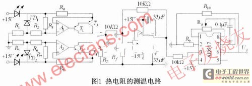
The temperature measurement circuit of the thermal resistor is shown in Figure 1. The circuit consists of a milliampere constant current source generation circuit, a differential operation circuit and an AD517 chip. The circuit uses two identical milliampere constant current sources to power the thermal resistor RT and the standard reference resistor Rf respectively. In the constant current source circuit, VD1 and VD2 are voltage-stabilizing diodes with temperature compensation, and four PNP transistors T1, T2, T3 and T4 form two PNP composite tubes, the purpose of which is to increase the gain of the amplifier and reduce the error, so as to improve the stability of the constant current source. The voltage generated by the circuit composed of the constant current source, RT, Rf (Rf is taken as Rf=100Ω) and ground is used as the input signal of the differential operation circuit. According to the composition of the circuit, it can be obtained that the output voltage of the differential operation circuit is proportional to the resistance value of the thermal resistor. By selecting appropriate component parameters, the temperature measurement range of the device is set to 0~120℃. The AD517 chip in this temperature measurement circuit is a high-precision, low-temperature drift monolithic integrated operational amplifier. ADS111O is the industry's smallest packaged 6-bit △-∑ type and an analog-to-digital conversion chip with an input voltage range of 0 to 2.048V. The function of the AD517 in the temperature measurement circuit is to adjust the output voltage of the differential operation circuit to a
The appropriate range is convenient for the subsequent ADS1110 to perform analog-to-digital conversion. In the figure, R9: and R10 are proportional amplifier resistors, and RP is the zero adjustment resistor of the integrated operational amplifier AD517, with a typical value of 20kΩ. The typical value of the output voltage adjusted by the amplifier circuit is Uo, which can be used as the input voltage of ADS1110, and after being converted into a digital signal by A/D, it is sent to the microcontroller for processing.

1.2 Overall Design
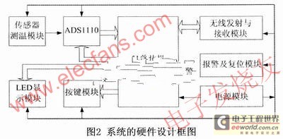
This high-precision temperature measuring device based on EL-700 platinum thermal resistance sensor can work as a single machine, and can also realize wireless data transmission between computers through wireless transceiver modules, and send the collected temperature signals to the computer for analysis, processing and printing, thereby realizing long-distance transmission and processing of data. The temperature measuring device is mainly composed of temperature signal detection and acquisition circuit, LED display, button control, power supply, alarm and reset, wireless transmission and reception and other functional modules. Each circuit module completes a certain function. The overall hardware composition block diagram of the temperature measuring device is shown in Figure 2.

The power module provides power for the entire device. In the stand-alone working mode, the EL-700 platinum thermal resistor temperature sensor is used to detect the temperature information of the object being measured. The output signal of the sensor is processed and amplified by the temperature measurement circuit module, and then converted into a digital signal by the analog-to-digital converter ADS1110 and sent to the single-chip microcomputer. The temperature display and control functions are realized by software programming; the LED digital tube display module is used to display the corresponding temperature value and temperature scale information; the device's working mode selection, Celsius temperature and Fahrenheit temperature display selection and other functions can be realized through the button control module and the corresponding program.
2 System software design
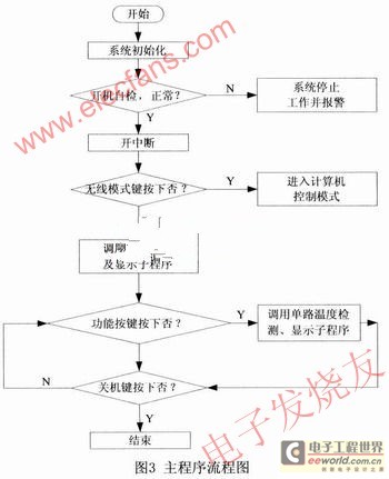
Software is the soul of the whole system. It is the key to the realization of system algorithms and functions. The whole temperature measurement system works under program control. In the software design of this system, we choose to use the single-chip C51 language as the main language, supplemented by assembly language, and adopt modular design ideas to divide this part of the design into corresponding program modules, which enhances the portability of the program. The whole software system mainly includes the single-chip main program, keyboard control subroutine, power-on self-test subroutine, temperature detection and display subroutine, interrupt subroutine, etc. The flow chart of the single-chip main program is shown in Figure 3. [page]

After the system is powered on, the microcontroller first initializes the system, and then the program executes the corresponding self-test subroutine to detect whether the temperature measurement system is faulty. The system defaults to the stand-alone working mode. In the stand-alone working mode, different functions can be selected according to the function keys, and the corresponding function key processing subroutine is called by the system to complete the corresponding function, and the corresponding temperature information is displayed on the LED digital tube, which has very good humanized characteristics; in the wireless working mode, the system acts as a lower computer and can communicate wirelessly with the remote computer to achieve long-distance data transmission, and use the powerful information processing function of the computer to analyze and process the data sent by the lower computer.
3 Test results and analysis
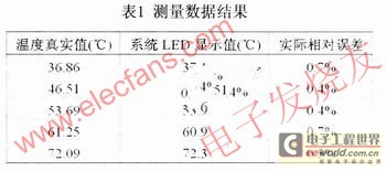
The test data is obtained by measuring the water temperature in the heating of an ordinary water heater. The indicated temperature of the experimental high-precision digital thermometer is used as the true value of the temperature detection point of the measured object. After the temperature information measured by this temperature measuring device is converted by the circuit and processed by the single-chip microcomputer, the displayed value of the measured temperature information on the LED digital tube is shown in Table 1. It can be seen from the data in the table that the LED display value of this system is very close to the true value; during the test, due to the influence of the measurement environment and other factors, the measured value of the system fluctuates around the true value, but the actual relative error of the temperature is always kept within 1%, which proves that this temperature measuring device can fully meet the actual measurement requirements.

4 Conclusion
In this paper, a high-precision temperature measuring device based on platinum thermal resistor is designed with a single-chip microcomputer as the control and data processing core of the temperature measuring device. It has two working modes. Two identical milliampere constant current sources are used to power the thermal resistor and the reference resistor respectively. The high-precision analog-to-digital conversion chip ADS1110 is used to complete the temperature information acquisition and A/D conversion, thereby improving the measurement accuracy of the device. The linearization algorithm and data processing operations are completed through the software programming of the single-chip microcomputer, and the function buttons are combined to realize the different functions of the system. The results of the experimental data show that this temperature measuring device has high measurement accuracy and has a very wide range of practical uses.
Previous article:Data Acquisition System for Railway Turnout Inspection
Next article:Design of a high-precision temperature measuring device
- Popular Resources
- Popular amplifiers
- Keysight Technologies Helps Samsung Electronics Successfully Validate FiRa® 2.0 Safe Distance Measurement Test Case
- From probes to power supplies, Tektronix is leading the way in comprehensive innovation in power electronics testing
- Seizing the Opportunities in the Chinese Application Market: NI's Challenges and Answers
- Tektronix Launches Breakthrough Power Measurement Tools to Accelerate Innovation as Global Electrification Accelerates
- Not all oscilloscopes are created equal: Why ADCs and low noise floor matter
- Enable TekHSI high-speed interface function to accelerate the remote transmission of waveform data
- How to measure the quality of soft start thyristor
- How to use a multimeter to judge whether a soft starter is good or bad
- What are the advantages and disadvantages of non-contact temperature sensors?
- Innolux's intelligent steer-by-wire solution makes cars smarter and safer
- 8051 MCU - Parity Check
- How to efficiently balance the sensitivity of tactile sensing interfaces
- What should I do if the servo motor shakes? What causes the servo motor to shake quickly?
- 【Brushless Motor】Analysis of three-phase BLDC motor and sharing of two popular development boards
- Midea Industrial Technology's subsidiaries Clou Electronics and Hekang New Energy jointly appeared at the Munich Battery Energy Storage Exhibition and Solar Energy Exhibition
- Guoxin Sichen | Application of ferroelectric memory PB85RS2MC in power battery management, with a capacity of 2M
- Analysis of common faults of frequency converter
- In a head-on competition with Qualcomm, what kind of cockpit products has Intel come up with?
- Dalian Rongke's all-vanadium liquid flow battery energy storage equipment industrialization project has entered the sprint stage before production
- Allegro MicroSystems Introduces Advanced Magnetic and Inductive Position Sensing Solutions at Electronica 2024
- Car key in the left hand, liveness detection radar in the right hand, UWB is imperative for cars!
- After a decade of rapid development, domestic CIS has entered the market
- Aegis Dagger Battery + Thor EM-i Super Hybrid, Geely New Energy has thrown out two "king bombs"
- A brief discussion on functional safety - fault, error, and failure
- In the smart car 2.0 cycle, these core industry chains are facing major opportunities!
- The United States and Japan are developing new batteries. CATL faces challenges? How should China's new energy battery industry respond?
- Murata launches high-precision 6-axis inertial sensor for automobiles
- Ford patents pre-charge alarm to help save costs and respond to emergencies
- New real-time microcontroller system from Texas Instruments enables smarter processing in automotive and industrial applications
- MLCC Noise Howling and Countermeasures
- Design of brushless DC motor driver based on hardware FOC TMC4671
- [ART-Pi Review] VI: Review of ATT-Pi's onboard Flash file system and FTP functions in RTT Studio environment
- Use transistor + MOS tube to control battery output
- Contemporary IoT smart antenna design trends | Review TE's exciting live broadcast, write a comment and win a gift!
- VLSI Digital Signal Processing Systems: Design and Implementation
- A foreign guy pranked: using ESP32 microcontroller disguised as GPU to infect his friend's computer with "ransomware"
- 13 Rules You Must Read for RF Circuit Power Supply Design
- Agilent6684A power supply maintenance method - Antai Instrument Maintenance
- General frequency converter technology of DSP

 LT1126CN8#PBF


 京公网安备 11010802033920号