The promise of driverless cars is no longer a pipe dream. Now, questions surrounding autonomous driving focus on the underlying technologies and advancements needed to make it a reality. LiDAR has become one of the most discussed technologies supporting the shift to autonomous driving, but many questions remain.
LiDAR can have a range of greater than 100 meters and an angular resolution of 0.1°. However, not all autonomous driving applications require this level of performance, applications such as valet parking assistance and street sweepers. There are a large number of depth sensing technologies that support these applications, such as radar, stereo vision, ultrasonic detection and ranging, and LiDAR. Each sensor has a unique trade-off between performance, size, and cost. Ultrasonic devices are the cheapest, but are limited in range, resolution, and reliability. Radar has greatly improved in range and reliability, but it also has angular resolution limitations; stereo vision can have significant computational overhead and accuracy limitations, as well as the need for proper calibration; LiDAR helps bridge these gaps, with accurate depth sensing, fine angular resolution, and low-complexity processing. However, LiDAR is often viewed as a bulky and costly product, which is not the case.
LiDAR design begins with determining the smallest object the system needs to detect, the reflectivity of that object, and the distance at which that object is located. This will define the angular resolution of the system. From this, the minimum achievable signal-to-noise ratio (SNR) is calculated, which is the true/false positive or negative detection criteria required to detect the target.
Understanding the perceived environment and the amount of information helps to make appropriate design trade-offs and achieve the best solution related to cost, performance, and development difficulty. For example, consider an autonomous vehicle traveling at 100 km/h compared to a logistics robot moving at 6 km/h. In high-speed situations, not only the vehicle traveling at 100 km/h must be considered, but also another vehicle traveling in the opposite direction at the same speed. For the perception system, this is equivalent to a relative speed approach of 200 km/h. For a LiDAR with a maximum detection distance of 200 meters, the vehicle can reduce the distance between objects by 25% in one second. It should be emphasized that the speed of the vehicle, the stopping distance, and the dynamics involved in performing evasion are unique complexities. In general, it can be said that LiDAR requires high-speed applications.
Resolution is another important characteristic in LiDAR system design. Good angular resolution enables a LiDAR system to receive multiple pixels of return signal from a single object. As shown in Figure 1, at a range of 200 meters, an angular resolution of 1° will translate into a pixel that is 3.5 meters on a side. This size pixel is larger than many of the objects that need to be detected, which poses some challenges. First, spatial averaging is often used to improve signal-to-noise ratio and detectability, but since there is only one pixel per target, this is not an option. In addition, even if detected, it is impossible to predict the size of the object. A piece of road debris, an animal, a traffic sign, and a motorcycle are typically smaller than 3.5 meters. In contrast, a system with an angular resolution of 0.1° has pixels that are 10 times smaller, or 35 cm, so this system may be able to distinguish between a car and a motorcycle.
Detecting whether an object is safe to drive over requires a higher resolution in elevation than in azimuth. Imagine how different the requirements would be for an autonomous logistics robot that is slow and needs to detect narrow but tall objects, like table legs.
The speed and performance of LiDAR can be determined in Figure 2. There are many options to choose from, such as scanning vs. flood array, or ToF vs. waveform digitization, and the choice between them is beyond the scope of this article.
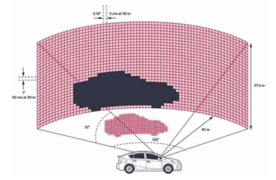
(Figure 1 A lidar system with 32 vertical channels horizontally scans the environment with an angular resolution of 1°.)
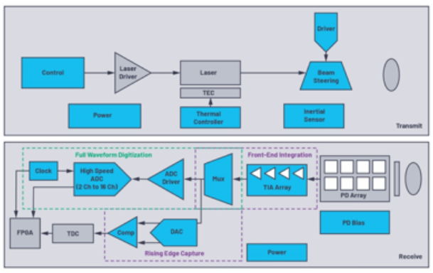
(Figure 2 Discrete components of a lidar system.)
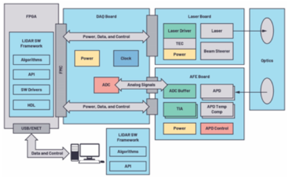
(Figure 3 ADI AD-FMCLIDAR1-EBZ LiDAR development solution system architecture)
Range or depth accuracy is related to the ADC sampling rate. Ranging accuracy allows the system to know exactly how far away an object is, which is critical in situations where close range movement is required, such as parking lots or warehouse logistics. Additionally, the change in range over time can be used to calculate velocity, a use case that typically requires better distance accuracy. Using a simple thresholding algorithm such as direct ToF, the achievable distance accuracy with a 1ns sampling period (i.e., a 1gsps ADC) is 15cm. The calculation is c(dt/2), where c is the speed of light and dt is the ADC sampling period. However, given that the ADC is included, more complex techniques such as interpolation can be used to improve ranging accuracy, which can be improved by roughly estimating the square root of the signal-to-noise ratio. One of the highest performance algorithms for processing data is to use a filter that maximizes the signal-to-noise ratio and then interpolate to achieve the best accuracy.
The AD-FMCLIDAR1-EBZ is a high-performance LiDAR prototyping platform featuring a 905nm pulsed ToF LiDAR development tool. The system can be used for robotics, drones, agricultural and construction equipment, and prototypes with 1D flood array scanning radars. The system uses a 905nm laser source driven by high-speed dual 4A MOSFETs. It also includes a programmable power supply powered by the LT8331 to power the First Sensor 16-channel APD array. There are multiple 4-channel LTC6561 transimpedance amplifiers with low noise and high bandwidth, as well as the AD9094 1 GSPS, 8-bit ADC, ensuring the lowest power consumption per channel of 435 mW/channel. It also supports additional bandwidth and sampling rate as needed, which helps to improve the overall system frame rate and ranging accuracy. At the same time, reducing power consumption is also important because the less heat dissipation, the simpler the thermal/mechanical design and the smaller the form factor.
Another tool for LiDAR design is the EVAL-ADAL6110-16, a highly configurable evaluation system. It provides a simplified, yet configurable, 2D flood array radar sensor for applications requiring real-time (65 Hz) object detection/tracking, such as collision avoidance, altitude monitoring, and soft landing.
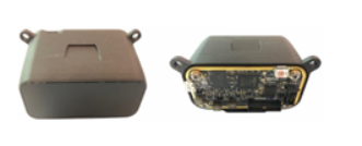
(Figure 4 The EVAL-ADAL6110-16 lidar evaluation module using the integrated 16-channel ADAL6110-16.)
The optics used in the reference design have a field of view (FOV) of 37° in azimuth and 5.7° in elevation. In a linear array of 16 pixels in azimuth, the pixel size at 20 meters is comparable to the average adult human being, which has an azimuth of 0.8 meters and an elevation of 2 meters. As mentioned previously, different applications may require different optical configurations. If the existing optics do not meet the needs of the application, the PCB can be easily removed from the housing and incorporated into a new optical structure.
The evaluation system is built around ADI's ADAL6110-16, a low-power, 16-channel, integrated LiDAR signal processor (LSP). The device provides timing control for detecting areas of interest, timing for sampling received waveforms, and the ability to digitize captured waveforms. The ADAL6110-16 integrates sensitive analog nodes, reducing noise, allowing the system to capture very low signal feedback, rather than implementing the same signal chain with discrete components with similar design parameters, where rms noise is the key factor affecting everything. In addition, the integrated signal chain allows the LiDAR system to reduce size, weight, and power consumption.
The system software can be quickly enabled, it is completely self-contained, powered by a USB 5V power supply, and can be easily integrated into a system with a Robot Operating System (ROS) driver. Users only need to create a connector to connect with a robot or vehicle, and support four communication protocols: SPI, USB, CAN or RS-232. The reference design can also be modified for different receiver and transmitter technologies.
As mentioned previously, the receiver data for the EVAL-ADAL6110-16 reference design can be modified to create different configurations, as shown in Figure 5 through Figure 7. The EVAL-ADAL6110-16 is equipped with a Hamamatsu S8558 16-photodiode array. The size of the pixels at different distances shown in Table 1 is based on the effective pixel size (i.e., 0.8 mm × 2 mm) and a 20 mm focal length lens. For example, if the same board is redesigned with a single photodiode such as the Osram SFH-2701, each with an active area of 0.6 mm × 0.6 mm, the pixel size at the same range will be different with the FOV varying based on the pixel size.

Table 1. Receiver dimensions and optics used in the EVAL-ADAL6110-16 and potential pixel arrangements if the receiver is changed to the SFH-2701

(Figure 5 Hamamatsu S8558 diode array.)
For example, let's look at the S8558, which has 16 pixels arranged in a straight line.
Pixel size: 2mm×0.8mm.
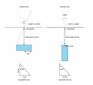
(Figure 6 Calculating angular resolution using basic trigonometry.)
After selecting a 20 mm focal length lens, the vertical and horizontal FOV for each pixel can be calculated using basic trigonometry, as shown in Figure 6. Of course, the choice of lens may involve additional, more complex considerations, such as aberration correction and field curvature. However, for a low-resolution system like this, straightforward calculations are sufficient.
The selected 1×16 pixel FOV can be used for applications such as object detection and collision avoidance for autonomous vehicles and autonomous ground vehicles, and for localization and mapping (SLAM) of robots in constrained environments such as warehouses.
Previous article:Allegro's New Advanced Hall-Effect Current Sensors Support Higher Currents and Bandwidths
Next article:Molex Launches RNC Sensor to Eliminate Harmful Noise and Reduce Driver Fatigue
Recommended ReadingLatest update time:2024-11-16 20:39

- Popular Resources
- Popular amplifiers
-
 LiDAR point cloud tracking method based on 3D sparse convolutional structure and spatial...
 -
 GenMM - Geometrically and temporally consistent multimodal data generation from video and LiDAR
 -
 Comparative Study on 3D Object Detection Frameworks Based on LiDAR Data and Sensor Fusion Technology
 -
 Dual Radar: A Dual 4D Radar Multimodal Dataset for Autonomous Driving
- Melexis launches ultra-low power automotive contactless micro-power switch chip
- Infineon's PASCO2V15 XENSIV PAS CO2 5V Sensor Now Available at Mouser for Accurate CO2 Level Measurement
- Milestone! SmartSens CMOS image sensor chip shipments exceed 100 million units in a single month!
- Taishi Micro released the ultra-high integration automotive touch chip TCAE10
- The first of its kind in the world: a high-spectral real-time imaging device with 100 channels and 1 million pixels independently developed by Chinese scientists
- Melexis Launches Breakthrough Arcminaxis™ Position Sensing Technology and Products for Robotic Joints
- ams and OSRAM held a roundtable forum at the China Development Center: Close to local customer needs, leading the new direction of the intelligent era
- Optimizing Vision System Power Consumption Using Wake-on-Motion
- Infineon Technologies Expands Leading REAL3™ Time-of-Flight Portfolio with New Automotive-Qualified Laser Driver IC
- Innolux's intelligent steer-by-wire solution makes cars smarter and safer
- 8051 MCU - Parity Check
- How to efficiently balance the sensitivity of tactile sensing interfaces
- What should I do if the servo motor shakes? What causes the servo motor to shake quickly?
- 【Brushless Motor】Analysis of three-phase BLDC motor and sharing of two popular development boards
- Midea Industrial Technology's subsidiaries Clou Electronics and Hekang New Energy jointly appeared at the Munich Battery Energy Storage Exhibition and Solar Energy Exhibition
- Guoxin Sichen | Application of ferroelectric memory PB85RS2MC in power battery management, with a capacity of 2M
- Analysis of common faults of frequency converter
- In a head-on competition with Qualcomm, what kind of cockpit products has Intel come up with?
- Dalian Rongke's all-vanadium liquid flow battery energy storage equipment industrialization project has entered the sprint stage before production
- Allegro MicroSystems Introduces Advanced Magnetic and Inductive Position Sensing Solutions at Electronica 2024
- Car key in the left hand, liveness detection radar in the right hand, UWB is imperative for cars!
- After a decade of rapid development, domestic CIS has entered the market
- Aegis Dagger Battery + Thor EM-i Super Hybrid, Geely New Energy has thrown out two "king bombs"
- A brief discussion on functional safety - fault, error, and failure
- In the smart car 2.0 cycle, these core industry chains are facing major opportunities!
- The United States and Japan are developing new batteries. CATL faces challenges? How should China's new energy battery industry respond?
- Murata launches high-precision 6-axis inertial sensor for automobiles
- Ford patents pre-charge alarm to help save costs and respond to emergencies
- New real-time microcontroller system from Texas Instruments enables smarter processing in automotive and industrial applications
- The power problem of the series resistance of the atomizer heating wire
- [GD32F310 Review] Interrupt test and GPIO usage
- As a newcomer, I don't seem to be qualified to make suggestions, but I still want to make a small suggestion!
- CMS32F033SS24 wireless charging and security chip
- The DTK28335 experimental box chip is very hot
- Have you ever used a fast charger using gallium nitride (GaN) technology?
- [HPM-DIY] HPM6750 peripheral LCDC driver RGB screen high frame rate video playback
- MSP430F149 small system development board realizes RS232 serial communication
- Xunwei IMX6 development board AndroidStudio-ledtest small light_test
- Help analyze this boost circuit


 LiDAR point cloud tracking method based on 3D sparse convolutional structure and spatial...


 京公网安备 11010802033920号