The power outages we have experienced were not too long, and any power grid failure in the city would be promptly remedied by repairmen. However, if the electricity transmitted across mountains and rivers to counties and towns was cut off, the line inspectors would have to follow the rivers and mountains to investigate. In ancient times, beacon towers have been replaced by radios at border posts. Now, wireless fault indicators have also built new beacon towers in smart grids.

Figure 1 Electric towers among mountains and rivers
my country's suburban and rural areas are vast and the settlements are scattered. The transmission lines covering the central cities are long and the environment is harsh. Manual maintenance is dangerous, inefficient and costly. According to the plan of the State Grid, 120 billion yuan has been invested in grid transformation in the past three years (2017-2015), mainly for Class D and E users (suburbs and rural areas), of which 20 billion yuan has been invested in distribution automation transformation. In the next three years, this trend will continue and deepen.

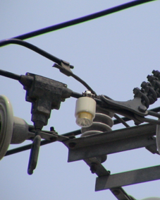
Figure 2 Fault indicator for overhead cables
Therefore, real-time monitoring of the operating status of large-area power grids, accurate knowledge of fault nodes and fault types, and the formation of a closed-loop automated repair indication system will have a direct impact on the intelligence level of smart grids, and there is a huge market involved.
Grid Fault Indication System Structure
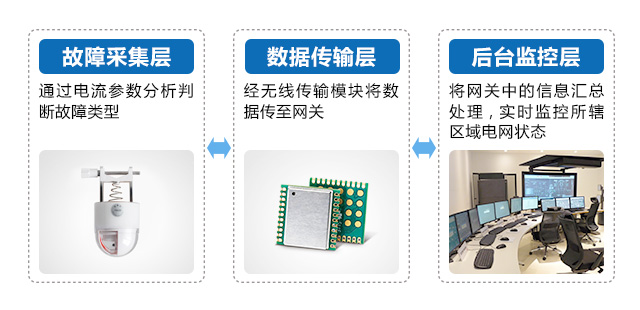
The power grid fault indication system has three layers, namely the fault collection layer, the data transmission layer, and the background monitoring layer. It consists of two parts: the fault collection sensor and the display. The sensor is responsible for detecting the current passing through the cable, and the display is responsible for judging the current information transmitted by the sensor and making fault indication actions. The judgment result is directly transmitted to the background monitoring layer through the data transmission layer, and maintenance personnel are directly dispatched to the fault node for emergency repair. The block diagram of the power grid fault indication system is shown in Figure 3.

Figure 3 Block diagram of power grid fault indication system
Due to the harsh working environment, the fault indicator needs to have the following three characteristics:
1. Low power consumption and long-term online operation
The use of protective coatings and shell materials can adapt to various environmental conditions, such as immersion in water, high salt spray and extreme heat and cold conditions, and can be installed outdoors or in cable branch boxes for a long time, requiring low power consumption of the equipment;

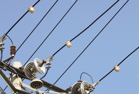
Figure 4 Fault indicator on overhead cable
2. Long and short distance fault indication
The fault information can be transmitted to the gateway through wireless transmission and summarized to the background to assign maintenance personnel. At the same time, it must be equipped with a high-brightness LED. When searching for faults and patrolling the lines at night, the fault alarm location can be accurately found within a range of 300m.
3. Automatic reset of fault indication
After a fault occurs, it will automatically reset at the set time in the absence of current and voltage, and will automatically return to normal state when power is supplied next time. At the same time, the abnormal information and reset state will be transmitted to the background through wireless communication.
Wireless data transmission layer solution:
Figure 5 ZM470SX-L data transmission scheme
Advantages of ZM470SX-L for power grid fault indication system
1. Low power consumption
The module integrates a +12dBm adjustable power amplifier and can achieve a receiving sensitivity of more than -110dBm. The link budget can meet most short-distance communication needs. It integrates the industry-leading power consumption control technology to minimize the power consumption of the module, making it very suitable for low-power applications with high power consumption requirements.
2. Industrial-grade quality, anti-interference
lIndustrial-grade quality can cope with various harsh environments such as high salinity, high temperature and humidity in coastal areas to ensure stable transmission.
3. Transmitting power is adjustable in multiple levels
The module integrates a power amplifier with a maximum power of 12.5dBm and provides multiple adjustable power levels from -8.5 to 12.5@Step 3dB. The signal coverage can be freely adjusted according to the remoteness of the fault indicator placement.
Similar apps
In addition to being used at the branches of overhead cable feeders, the power grid fault indicator can also be directly installed on box-type transformers, various ring network cabinets, cable branch boxes, and substation inlet and outlet lines.
Previous article:The secret to staying one step ahead with Bluetooth 5
Next article:Nordic Semiconductor begins sampling nRF91 Series low-power cellular IoT
Recommended ReadingLatest update time:2024-11-16 19:43

- Popular Resources
- Popular amplifiers
- e-Network Community and NXP launch Smart Space Building Automation Challenge
- The Internet of Things helps electric vehicle charging facilities move into the future
- Nordic Semiconductor Launches nRF54L15, nRF54L10 and nRF54L05 Next Generation Wireless SoCs
- Face detection based on camera capture video in OPENCV - Mir NXP i.MX93 development board
- The UK tests drones equipped with nervous systems: no need to frequently land for inspection
- The power of ultra-wideband: reshaping the automotive, mobile and industrial IoT experience
- STMicroelectronics launches highly adaptable and easy-to-connect dual-radio IoT module for metering and asset tracking applications
- This year, the number of IoT connections in my country is expected to exceed 3 billion
- Infineon Technologies SECORA™ Pay Bio Enhances Convenience and Trust in Contactless Biometric Payments
- Innolux's intelligent steer-by-wire solution makes cars smarter and safer
- 8051 MCU - Parity Check
- How to efficiently balance the sensitivity of tactile sensing interfaces
- What should I do if the servo motor shakes? What causes the servo motor to shake quickly?
- 【Brushless Motor】Analysis of three-phase BLDC motor and sharing of two popular development boards
- Midea Industrial Technology's subsidiaries Clou Electronics and Hekang New Energy jointly appeared at the Munich Battery Energy Storage Exhibition and Solar Energy Exhibition
- Guoxin Sichen | Application of ferroelectric memory PB85RS2MC in power battery management, with a capacity of 2M
- Analysis of common faults of frequency converter
- In a head-on competition with Qualcomm, what kind of cockpit products has Intel come up with?
- Dalian Rongke's all-vanadium liquid flow battery energy storage equipment industrialization project has entered the sprint stage before production
- Allegro MicroSystems Introduces Advanced Magnetic and Inductive Position Sensing Solutions at Electronica 2024
- Car key in the left hand, liveness detection radar in the right hand, UWB is imperative for cars!
- After a decade of rapid development, domestic CIS has entered the market
- Aegis Dagger Battery + Thor EM-i Super Hybrid, Geely New Energy has thrown out two "king bombs"
- A brief discussion on functional safety - fault, error, and failure
- In the smart car 2.0 cycle, these core industry chains are facing major opportunities!
- The United States and Japan are developing new batteries. CATL faces challenges? How should China's new energy battery industry respond?
- Murata launches high-precision 6-axis inertial sensor for automobiles
- Ford patents pre-charge alarm to help save costs and respond to emergencies
- New real-time microcontroller system from Texas Instruments enables smarter processing in automotive and industrial applications
- Voltage controlled current source composed of opa547
- [GUIX①, one of threadX components] guix text button
- Qorvo Technology Video: GaN Solutions for Sub-6 GHz 5G Base Station Applications
- [Jihai M3 core APM32E103VET6S MINI development board] 02. USART online interaction function
- PCB design of RF devices
- [TI star products limited time purchase] TI's latest shopping experience
- Please help me choose STM8L151 or STM32L051
- R5F1056A Device file not found
- Help! How to view the pin definition in the Keil file for the STM32F103C8T6 chip?
- Popular Science丨Six Elements of Brushless DC Motor Control

 Application of LoRa on Raspberry Pi
 Comparison of Lora, 433MHz, 4G and Wi-Fi communication technologies


 京公网安备 11010802033920号