Siren signal generator circuit
Source: InternetPublisher:闪电杰克 Keywords: signal generator generator circuit oscillator pulse Updated: 2021/01/08

Siren signal generator circuit
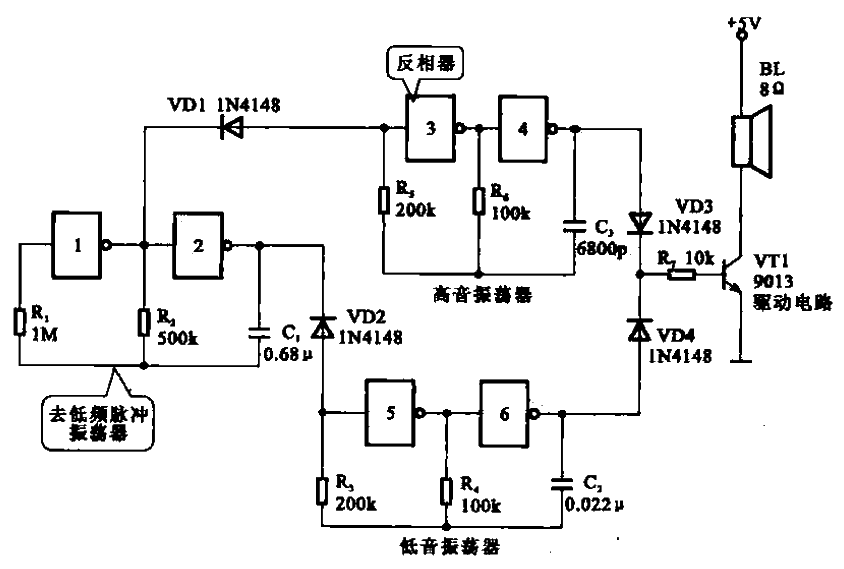
Shown is a siren signal generator circuit consisting of a six-inverter integrated circuit CD4069 . Inverters 1 and 2 form an
ultra-low frequency pulse oscillator , and NOT gates 3 and 4 form a high-frequency oscillator. NOT gates 5 and 6 form a bass oscillator. The output of the ultra-low frequency pulse
oscillator
controls the high and low frequency oscillators to oscillate in turn through the diodes VDI and VD2. The oscillation signals are
amplified by the semiconductor transistor VT1 through VD3 and VD4 respectively, and then drive the siren sound from the speaker.
- Analysis of the working principle of CMOS/CCD image sensor
- Why Do Amplifier Fuses Blow? How Do You Prevent Amplifier Fuses from Blowing?
- Working principle and truth table of JK flip-flop
- What is a D flip-flop and how does it work?
- How to Build a Simple Temperature Indicator Circuit Using NTC and PTC Thermistors
- Why use PWM? What are its advantages?
- What is the difference between high-side and low-side resistive current sensing
- Presettable 8-bit counter circuit
- Odd-frequency counter with symmetrical output waveform (μL9020)
- Rectangular Pulse Frequency Doubler
- Single power supply signal generator circuit diagram
- Adjustable pulse generator circuit
- Digital timer with one digit display
- Signal generator circuit with small distortion
- 555 various signal generator circuit diagrams
- Transmitting TV/radio dual-purpose signal generator circuit
- 465kHz IF signal generator circuit
- Two examples of 60Hz time base signal generator circuit circuit-a
- simple tv signal generator
- 20HZ signal generator


 京公网安备 11010802033920号