How to Make a Buzz Wire Game Using Arduino
Source: InternetPublisher:通通 Keywords: buzzer Arduino game design Updated: 2024/12/24
Arduino is very popular for building hobby projects and games, we have previously built Snake game, Pong game, Space Race game etc. using Arduino. Today we are building a more popular game using Arduino- Buzz Line Game or Steady Hand Game.
For this project, we will use an Arduino Uno, a buzzer, and two aluminum wires. A 16x2 LCD is also used to display the game status. The two ends of the maze wire will be connected to the digital pins 2 and 3 of the Arduino, and the handle wire is connected to the ground pin of the Arduino. The digital pin is defined as the INPUT_PULLUP pin. So when the handle wire touches the maze wire, the digital pin state becomes low and the buzzer sounds.
The diode is connected at the end of the maze wire so when you pass over this diode and touch the maze wire with the round handle wire, only one pin (pin 3) will go low. In this case, a congratulatory text (well done) will be displayed on the LCD.
Required Components
Arduino
Aluminum wire
16x2 LCD
I2C module
Breadboard
buzzer
diode
Circuit Schematic

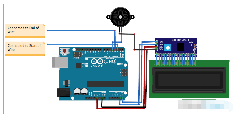
The circuit diagram of Arduino Buzz Wire Game is given above. The SCL and SDA pins of the I2C module are connected to the A5 and A4 pins of Arduino, while the V CC and GND pins of the I2C module are connected to the 5V and GND pins of Arduino. The positive rail of the buzzer is connected to the digital pin 4 of Arduino and the negative rail is connected to GND. Cut the aluminum wire and bend it into a zigzag shape. Solder a diode on one end of the wire. Then cut another wire to make a handle and bend one end into a loop.
16x2 LCD can also be connected with Arduino without using I2C module.
Connect the D2 and D3 pins of Arduino to the two ends of the Zig-Zag wire and connect the handle wire to the GND pin of Arduino.

Code Description
The complete code for this Arduino Buzz Wire game is given at the end of the document.
Start your code by including the library files of LCD module. LiquidCrystal_I2C.h library is used for I2C communication between Arduino and LCD module .
#include
After that, define the Arduino pin of the buzzer, the starting point of the wire, and the end point of the wire.
Constant int start
Then define two variables start & end_. These variables will be used to hold the readings of the wires.
integer start, end_;
Now define the buzzer pin as an output and the wiring pin as INPUT_PULLUP. The Arduino has internal pull-up resistors with a value of ~20k ohms. These resistors can be connected internally using INPUT_PULLUP. Defining INPUT_PULLUP is functionally the same as connecting a ~20k ohm resistor between the pin and +5V.
pinMode(buzzer, OUTPUT);
pinMode(startPin, INPUT_PULLUP);
pinMode(startPin, INPUT_PULLUP);
Inside the void loop, read the state of the line pin.
start = digitalRead(startPin);
end_ = digitalRead(endPin);
Now compare the readings of the wire pins. If both pins are low, it means you have touched the wire so the buzzer will sound, if the start pin of the wire is high and the end pin is low, it means you have reached the end point.
if (start == low && end == low) {
    digitalWrite(buzzer, HIGH);
    delay(1000);
    digitalWrite(buzzer, LOW);
    lcd.setCu
Testing the Buzz Wire Game
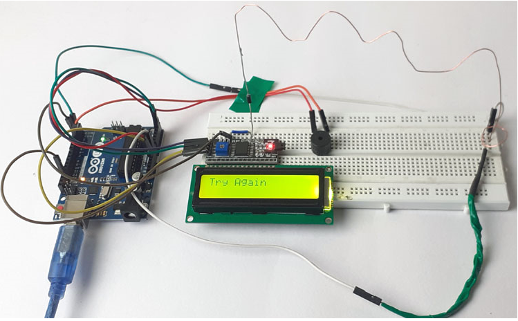
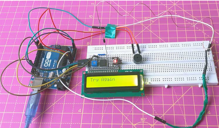
After connecting the hardware and uploading the given code, you can start playing the game. So, hold the wire with the circle in your hand and try to solder the wire with the circle all the way to the diode through the zigzag wire without letting the circle wire touch anywhere. If you touch the wire, then the buzzer will sound and the LCD will display "Try Again". If you complete the game without touching the wire, then it will display "Good Job".

#include
- How to Unlock Your Windows Laptop Using an RFID Tag
- DIY an indoor and outdoor webcam
- Analysis of the circuit principle of ZX5-630 welding machine
- Circuit diagram of intermittent cockroach killer
- Production of electric mosquito killer
- Design of smart radiator valve for home based on Raspberry Pi
- DIY Solar Detector
- How to Build a Low-Cost Arduino MiniCNC Plotter
- High power laser constant current drive circuit
- Ultrasonic electronic guide circuit
- Microcontroller buzzer control program and drive circuit diagram
- Thyristor type answering circuit three
- Prevent misoperation of control circuits in both places
- Three-phase power supply phase sequence dedicated circuit
- Photosensitive buzzer circuit
- Driver buzzer application circuit with 5 flashing LEDs
- Buzzer replacement circuit for low light lamp
- Multi-tone buzzer circuit
- Touch type single chip flash-buzzer
- Alarm buzzer with a loudness of 110DB


 京公网安备 11010802033920号