How to Build a Smart Knock Detection Door Lock Using Arduino
Source: InternetPublisher:张小哥 Keywords: security system buzzer Arduino Updated: 2024/12/31
Security is a major concern in our daily life and digital locks have become an essential part of these security systems. There are many types of security systems that can be used to protect our places. Some examples are PIR based security systems, RFID based security systems, digital lock systems, bio-matrix systems, electronic code locks. In this post, let us build a secret knock detection door lock using Arduino which detects your knock pattern and opens the lock only when the knock pattern matches the correct pattern.
Components:
- Arduino Uno
- Button
- buzzer
- 1M Resistor
- that power
- Connection line
- box
- Servo Motor
Circuit Description:
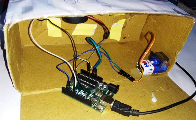
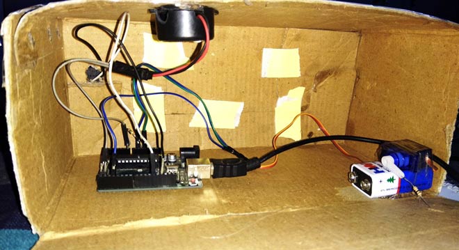
The circuit diagram of this knock pattern detector is very simple which contains Arduino, push buttons, buzzer and servo motor to control the whole process of the project. Arduino controls the whole process like getting the password from the buzzer or sensor, comparing the pattern, driving the servo to open and close the door and save the pattern to the Arduino.

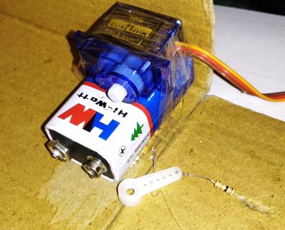
The push button is directly connected to pin D7 of Arduino with respect to ground. The buzzer is connected on analog pin A0 of Arduino with respect to ground and a 1M resistor is also connected between A0 and ground . The ** Servo motor** is also connected to PWM pin D3 of Arduino .


Feeding knock mode in Arduino:
In this circuit, we use a buzzer or Peizo sensor to get the knock input pattern in the system. Here, we use a button to allow taking the input from the sensor and save it into the Arduino. This system is designed by taking inspiration from the Morse code pattern, but it is not exactly the same as this.
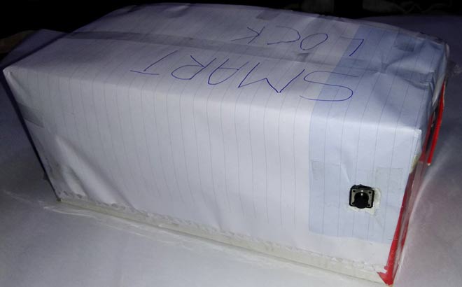
Here, we have used a cardboard box for demonstration. To get the input, we knocked over the board after pressing the button. Here, we knocked over the board by keeping in mind a time period i.e. 500 milliseconds. This 500ms is because we have fixed it in the code and the input mode depends on it. This 500ms time period will define the input as 1 or 0. Check the code below to understand this.

When we tap it, the Arduino starts monitoring the time from the first tap to the second tap and puts it into an array. In this system, we tapped it 6 times. This means we will get 5 time periods.
Now we check the time periods one by one. First, we check the time period between the first tap and the second tap, if the time difference between them is less than 500ms, then it will be 0, if it is more than 500ms, it will be 1 and save it into a variable. Now, after it, we check the time period between the second tap and the third tap and so on.
Finally, we will get a 5-bit digital output in 0 and 1 format (binary).
Job Description:
The working of the knock based smart lock project is simple. First, we have to save a pattern in the system. So, we have to hold the button until we knock 6 times. In this project, I have used 6 knocks but the user can change it as per their requirement. After six knocks, the Arduino finds the knock pattern and saves it in the EEP ROM. Now after saving the input pattern, press and immediately release the button which is used to transfer the input from the sensor to the Arduino to open the lock. Now we have to knock 6 times. After that, the Arduino decodes it and compares it with the saved pattern. If a match occurs, then the Arduino opens the door by driving the servo motor.

Note: When we hold the button Arduino starts 10 seconds timer to take all 6 knocks. It means user needs to knock within this 10 seconds. And user can open the serial monitor to see the logs.
Programming Instructions:
In the program, first, we include the header file and define the input and output pins and define the macros and declared variables as shown in the complete code section in the code below.
After this, in the setup function we instruct the defined pins and start the servo motor.
void setup()
{  pinMode(sw, INPUT_PULLUP);  myServo.attach(servoPin);  myServo.write(180);  Serial.begin(9600);
}
After that, we take the input and save the input pattern or knock time in an array.
void loop()
{   int i=0;   if(digitalRead(sw) == LOW)
   {
      Serial.println("Start");
      delay(1000);      long stt= millis();      while(millis()<(stt+patternInputTime))
      {int temp=analogRead(A0);if(temp>sensitivity && flag==0 && i<=patternLenth)
        {
.... .
..... ....
Afterwards, we decode the input pattern
for(int i=0;iIf the button is still pressed, save
if(digitalRead(sw) == 0)
      {         for(int i=0;i
If the button is still not pressed then the Arduino compares the input decoded pattern to the saved pattern.
else  {         if(knok == 1)
         {for(int i=0;i
If any of the passwords match then the servo opens the door, otherwise nothing happens but the user may see the result through the serial monitor.
Serial.println(acceptFlag);         if(acceptFlag >=  patternLenth-1)
         {
             Serial.println(" Accepted");
             myServo.write(openGate);
             delay(5000);
             myServo.write(closeGate);
         }         elseSerial.println("Rejected");
      }<p>#include<EEPROM.h><br/>#include<Servo.h>p><p>#define patternLenth 5<br/>#define patternInputTime 10000<br/>#define sensitivity 80<br/>#define margin 100<br/>#define sw 7<br/>#define servoPin 3<br/>#define openGate 0<br/>#define closeGate 180<br/>long slot[patternLenth+1];<br/>int pattern[patternLenth];<br/>int flag=0;<br/>int acceptFlag=0;<br/>int knok;p><p>Servo myServo;p><p>void setup() <br/>{<br/>
  pinMode(sw, INPUT_PULLUP);<br/>
  myServo.attach(servoPin);<br/>
  myServo.write(180);<br/>
  Serial.begin(9600);<br/>}p><p>void loop() <br/>{<br/>
   int i=0;<br/>
   if(digitalRead(sw) == LOW)<br/>
   {   <br/>  Serial.println("Start");<br/>  delay(1000);<br/>  long stt= millis();<br/>  while(millis()<(stt+patternInputTime))<br/>  {<br/>int temp=analogRead(A0);<br/>if(temp>sensitivity && flag==0 && i<=patternLenth)<br/>{<br/> delay(10);<br/> flag=1;<br/> slot[i++]=millis()-stt;<br/> //Serial.println(slot[i-1] - stt);<br/> if(i>patternLenth)<br/> break;<br/>}p><p>        else if(temp == 0)<br/>flag=0;<br/>  }<br/>  <br/>  long stp=millis();<br/>  Serial.println("Stop");<br/> // Serial.println(stp-stt);<br/>  for(int i=0;i<patternLenth;i++)<br/>  {<br/> knok=1;<br/> if(slot[i+1]-slot[i] <500 )<br/>pattern[i]=0;<br/> else<br/>pattern[i]=1;<br/> Serial.println(pattern[i]);<br/>  }p><p>      if(digitalRead(sw) == 0)<br/>  {<br/> for(int i=0;i<patternLenth;i++)<br/>EEPROM.write(i,pattern[i]);<br/> while(digitalRead(sw) == 0);<br/>  }p><p>      else<br/>  {<br/> if(knok == 1)<br/> {<br/>for(int i=0;i<patternLenth;i++)<br/>{<br/>   if(pattern[i] == EEPROM.read(i))<br/>   {<br/>  Serial.println(acceptFlag++);<br/>   }p><p>               else<br/>   {<br/>Serial.println("Break");<br/>break;                <br/>   }<br/>}<br/> }p><p>         Serial.println(acceptFlag);<br/> if(acceptFlag >=  patternLenth-1)<br/> {<br/> Serial.println(" Accepted");<br/> myServo.write(openGate);<br/> delay(5000);<br/> myServo.write(closeGate);<br/> }<br/> else<br/>Serial.println("Rejected");<br/>  }p><p>      for(int i=0;i<patternLenth;i++)<br/>  {<br/> pattern[i]=0;<br/> slot[i]=0;<br/>  }<br/>  slot[i]=0;<br/>  acceptFlag=0;<br/>
   }<br/>}p>
- Detailed explanation of the working principle of the parking light circuit
- Interpretation of CAN bus driving recorder system circuit
- Mono LB1405 level indication circuit
- LJ2 series transistor proximity switch principle circuit diagram
- Telephone line protection alarm circuit
- Computer host overheating alarm circuit
- Infrared blind cane circuit diagram
- Catillac luggage compartment closing circuit diagram
- Stapler control circuit
- Electronic ventriloquist circuit
- Microcontroller buzzer control program and drive circuit diagram
- Thyristor type answering circuit three
- Prevent misoperation of control circuits in both places
- Three-phase power supply phase sequence dedicated circuit
- Photosensitive buzzer circuit
- Driver buzzer application circuit with 5 flashing LEDs
- Buzzer replacement circuit for low light lamp
- Multi-tone buzzer circuit
- Touch type single chip flash-buzzer
- Alarm buzzer with a loudness of 110DB


 京公网安备 11010802033920号