How to make a remote control car
Source: InternetPublisher:张七岁 Keywords: Remote control car remote control Updated: 2025/01/14
A remote control car also called RC car is something every electronics hobbyist likes to build. But most of them don't know where to start and how to build it, and some are even deceived by its complicated appearance. The focus of this article is to guide hobbyists to build their own homemade RC car with minimal components.
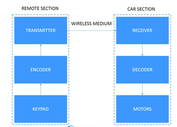
Block Diagram:

To make a remote control car, we need to make sure these blocks are available. The above modules are divided into two parts: remote and car
For the purpose of understanding. Start with the keyboard that controls the movement of the car, while the encoder and decoder are designed to encode and decode the movement signals for secure transmission. The transmitter also sends the movement signals over the wireless medium and the receiver gets the signal at the destination.
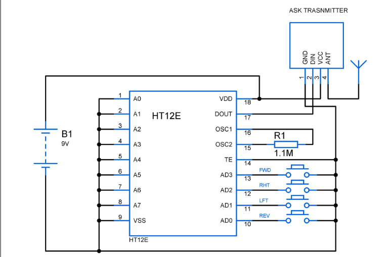
Remote control circuit diagram:

The above remote control circuit consists of three important components: keyboard, encoder IC HT12E and RF transmitter RF433 module.
keyboard:
The keypad of the remote control consists of four individual buttons which are connected to the data pins AD0 to AD3 of the encoder IC. When these buttons are pressed, it passes the motion signal to the encoder,
Encoder
HT12E: This encoder is used to encode the motion signals fed by the individual buttons. The data pins AD0 to AD3 are active low, so pressing the button closes the circuit and a logic 1 or high signal is fed to these pins. It also contains the address pins A0 to A7, which allow us to try different address combinations to ensure the safety of data transmission, but make sure you use the same address combination in the receiving end (decoder). In the above circuit, we did not try any address combination, so all the pins were connected to ground. Dout
The pin provides the encoded output data.
RF433 TX: This is a simple RF433
TX module, operating at 433MHz. The encoded data from the encoder is fed to the DIN pin of TX and a simple antenna is connected to its 4th pin.
Oscillator Frequency: The oscillator frequency of the HT12E is 3.25Khz (see the graph of oscillation frequency vs. supply voltage in the datasheet). This frequency is fixed with resistor R1 (1.1M). Modifying this resistor value will change the output frequency.
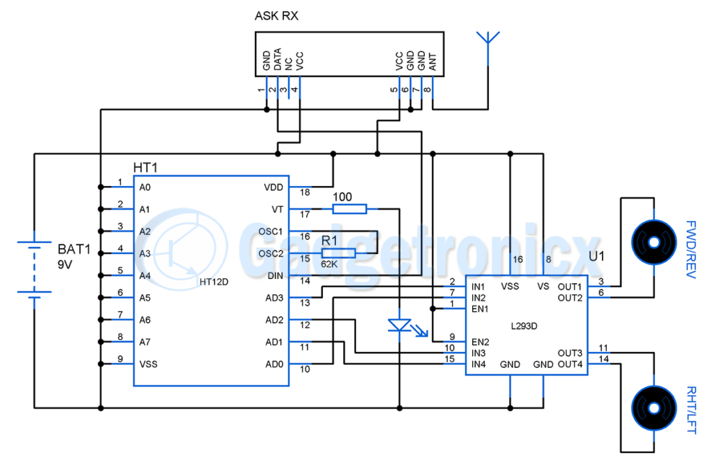
Remote control car circuit diagram:

RF433 Receiver: This is a simple RF433
RX module, the operating frequency is 433MHz. The received coded data signal is received through the antenna, the signal is obtained from the DATA pin and fed to the decoder.
HT12D Decoder: The encoded signal from the RX module is fed to the DIN of the decoder
pin. The signal is then decoded by the decoder, if any, remember to use the same address combination used in the encoder, otherwise the motion signal will be misinterpreted. The decoder also includes a VT pin, which is used as an identification if any RF link is established, an LED is connected to this pin for identification.
Oscillation frequency: In order to successfully receive and decode the input signal, the HT12D oscillation frequency should be 50% of the encoder oscillation frequency.
times. In our case, the HT12E oscillates at 3.25Khz, so our decoder should oscillate at 162.5Khz. Fixing the value of R1 to 62K will do the job (see the oscillation frequency vs. supply voltage graph in the datasheet).
L293D: This IC is used as a bi-directional motor driver. It is highly impossible to drive heavy loads like motors using a decoder IC, so we have used a dedicated L293D for this purpose.
IC. Read more about the working of L293D.
Motors: Two simple DC motors are used for the movement of the RC car. One motor is used to move the car forward and backward while the other is used to steer the car left and right.
Remote control car movement mechanism:
We have completed the remote control and the circuit that is going to be placed inside the car. Now, the next important thing is to provide the mechanism to move our RC car forward and backward. Fix the gears to the motor and the rails connecting the rear wheels. Fix the motor close to the gears in the rails so that when the motor moves the car moves forward. Similarly, when the motor rotates in the opposite direction, the car should move backward.
Automobile steering mechanism:
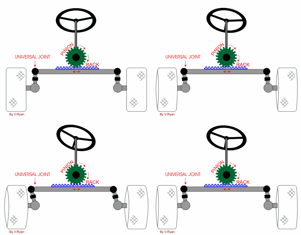
The steering mechanism is a bit trickier than the motion mechanism as it requires some mechanics. There are several steering mechanisms used while building RC cars but here I prefer to use a "rack and pinion" arrangement to steer the car in the direction we want it to go.

The above animation shows the working of the rack and pinion steering mechanism. Here, the pinion will be connected to our front motor which is responsible for right/left steering. So, when this motor moves in clockwise direction, the car turns left and vice versa.
Parts Required:
RF433 MHz TX and RX
Encoder HT12E and Decoder HT12D
L293D – 1
Motors – 2
Wheels – 4
Resistors – As needed
Light Emitting Diode
Hopefully you found this project helpful. Check out other electronics projects on our website. If you have any feedback or comments about this project, please leave them in the comments section below.
- Production of Wireless Proportional Motor Remote Control
- DIY wireless mouse or keyboard
- Analysis of multi-purpose remote control alarm controller
- Multi-channel wireless remote control circuit (F36-F/F36-J)
- Remote control infrared detection circuit
- Electric model aircraft remote control device
- Ceiling fan wireless remote control circuit
- Multiple remote control
- Electric single beam crane radio remote control (TX315B1)
- Color TV remote control 10
- Infrared remote control switch circuit diagram composed of CD4017
- Coal stove door automatic opening remote control circuit
- Remote control circuit b composed of RX5019 and RX5020
- Dimming remote control circuit
- Telephone remote control circuit
- BX2-500 arc welding machine remote control circuit wiring
- Toy remote control car battery charger circuit
- LB1475 (video recorder) two-wire wired remote control circuit
- High frequency remote control circuit design circuit diagram
- light bulb remote control circuit


 京公网安备 11010802033920号