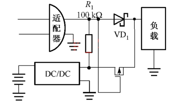
Battery powered switching circuit diagram
Source: InternetPublisher:风向双子座 Keywords: Switching circuit battery powered Updated: 2024/08/09
Battery powered switching circuit diagram (I)
In a dual power supply system consisting of AC power and battery, the simplest way to switch power is to use two Schottky diodes to isolate the two power supplies, as shown in Figure 1.
This circuit requires that the output voltage of the AC adapter must be higher than the output voltage of the battery DC/DC conversion. When the AC adapter is connected, the diode VD2 is reverse biased, prohibiting the current from flowing from the battery to the load. When the AC power is removed, the diode VD1 prevents the current from flowing from the battery to the adapter.
This solution is simple in design and occupies a small area of the printed circuit board. However, it has two disadvantages: the forward voltage of VD2 (about 0.4V) reduces the output voltage of the DC/DC. If the output voltage is lower than the starting voltage, this solution will not be applicable;
In addition, the forward voltage of VD2 also wastes the power of the battery. The power dissipated by diode VD2 is equal to the load current multiplied by the forward voltage drop.

In Figure 2, a P-channel MOSFET is used to replace the diode VD2 in Figure 1. When switching to the battery, the MOS-FET is turned on and the battery supplies power to the load. When the AC adapter is connected, the gate voltage of the MOSFET is higher than its source voltage and it is in the off state, thus cutting off the connection between the battery and the load.
For a load current of 100mA, a P-channel MOSFET with an on-resistance of 50mD has a voltage drop of 0.5mV and consumes only 0.5mW. The diode configuration shown in Figure 1 has a voltage drop of 400mV and a power loss of 40mW. The on-resistance of a MOSFET depends on its gate bias.
In Figure 2, when the AC power is removed, the gate voltage of the MOSFET is zero and the source is the battery voltage. The on-resistance of the MOSFET should be low enough under this bias to ensure that the desired output voltage can be obtained under the maximum load current. Therefore, a MOSFET with a low threshold should be selected as much as possible.

Battery power switching circuit diagram (II)
The schematic diagram is as follows, power supply label description:
1. VCC_5V0 external power input
2. LI_BAT lithium battery
3. VCC_SYS main power output
4. VCC_SB standby power output
Control interface description:
1. EX_PWR_KEY switch button input, external touch switch or self-locking switch, low level is valid.
2. PWR_KEY_DET switch button detection is used for the microcontroller to detect the switch status, mainly suitable for using light touch switches.
3. SYS_PWR_HOLD power hold, high level is valid, useful when using a touch switch or the system wants to control the shutdown by itself
Typical applications:
1. The power switch uses a touch switch. By detecting the PWR_KEY_DET state, control SYS_PWR_HOLD to achieve long press for xx seconds to turn on the system, and long press for xx seconds to shut down the system.
2. Vehicle-mounted equipment, D17 is connected to the ACC signal to realize the car ignition, the equipment automatically starts, the car is turned off, and it automatically shuts down after a delay of xx time.
3. Use a self-locking switch, disconnect D17, and do not use PWR_KEY_DET and SYS_PWR_HOLD to achieve automatic switching between external power supply and built-in power supply, and a small self-locking switch to control the on and off of large current.

- How about the boost converter TPS61299?
- 220V Remote Load Monitor
- Use pulse width modulation to get a precise output voltage
- Constant current LED lamp driver circuit with soft start and anti-shock
- Parallel DC regulated power supply circuit diagram
- Dual forward converter schematic diagram
- UC3842 Electric Vehicle Charger
- Circuit diagram explanation: simple switching power supply circuit diagram
- Battery powered switching circuit diagram
- Automatic charger made with LM3914
- STR5412 power circuit
- Power circuit a composed of intelligent thyristor modules
- 4-phase CPU power circuit using HIP6301 and HIP6602 chips
- Motor frequency converter power frequency-variable frequency switching circuit
- One of the transistor stabilized current power supply circuits
- Automatic switching circuit for motor Y-△ connection
- 3V battery power supply output +-5V voltage stabilization circuit diagram
- AC and DC inflow automatic switching circuit diagram
- Battery Powered High Voltage Generator Circuit
- Power switching circuit diagram


 京公网安备 11010802033920号