· 1 Introduction
· 2.Team introduction
· 3. Question requirements
· 4.Project introduction
· 5. Specific design
· 6.Test results
· 7. Summary
The results of the electronic competition finally came out. When I was informed that the national competition was promoted, I was so excited that I couldn't sleep all night (it was really lucky). The national second grade is already the best result for us. Let's continue to settle down.
While celebrating, Lichuang happened to launch this open source event again. At Lichuang’s invitation, we will open source this project.
Our team comes from the electronic information major, and the team configuration is two hardware designers and one software designer.


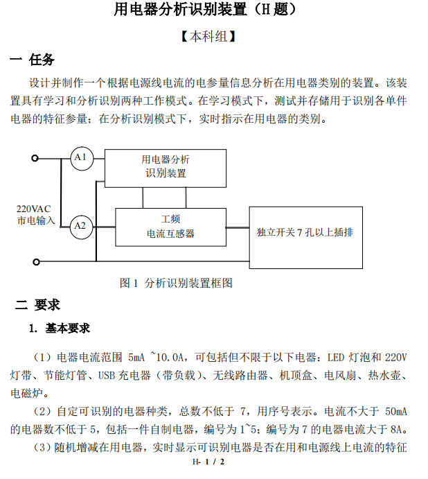
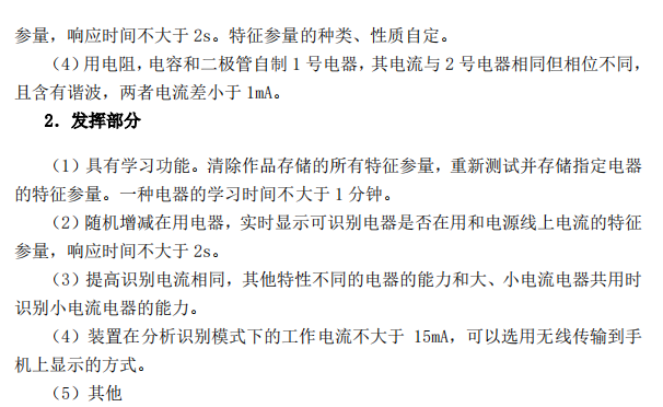
This question requires the design and production of a device that analyzes the category of electrical appliances in use based on the electrical parameter information of the power line current. The device has two working modes: learning and analysis and recognition. In the learning mode, the characteristic parameters used to identify each single electrical appliance are tested and stored; in the analysis and recognition mode, the category of the electrical appliance in use is indicated in real time.
The key points and difficulties are:
1. The power grid has a large fluctuation range at different times and locations, which will affect the measurement of high-power electrical appliances, so that the power fluctuation can be as high as ±50W , which brings great difficulty to the accurate identification of electrical appliances.
2. When measuring the combination of high-power electrical appliances and low-power electrical appliances, the spectrum characteristics of the high-power electrical appliances will cover up the low-power spectrum characteristics, making identification extremely difficult.
3. How to identify electrical appliances with the same current but different impedance characteristics.
4. The choice of electrical appliances needs to be carefully considered. A good combination of electrical appliances will make your initial test result much better.
This system solution mainly uses the STM32_F103 microcontroller as the system main control. The current transformer converts the large current into a small current, uses a resistor to output the voltage, and then uses the AD637 to output the effective value, and finally sends it to the stm32 microcontroller. The single-chip microcomputer obtains electrical parameters such as active power, voltage, and current, and uses these parameters to perform the electrical appliance identification function. Finally, the single-chip microcomputer displays the judgment results, current, voltage, etc. on the serial port screen in real time.
(The three modules at the top of the picture are all voltage reducing modules that provide a voltage value of 3.3V to the microcontroller. Since the USB interface is subsequently used to power the microcontroller, these three voltage reducing modules are useless.)
AD637 typical application diagram
AD637 adopts a high-precision, high-bandwidth true RMS detection device. Its function is to convert the RMS of external input AC signals into DC signal output , and can calculate the true RMS of various complex waveforms. The measurable effective value of the input
signal can be up to 7V. For a 1vRMS signal, its 3dB bandwidth is 8MHz, and the level of the input signal can be indicated in dB .
The current transformer consists of a primary coil, a secondary coil, an iron core, an insulating support and an outlet terminal. Its primary coil is connected in series with the main circuit, and through the measured current I1 , it generates alternating magnetic flux in the iron core, causing the secondary coil to induce
Outputs the corresponding secondary current I2 . If the excitation loss is ignored, then I1N1=I2N2 , where N1 and N2 are the turns of the primary and secondary coils respectively. The current transformer ratio K=I1/I2=N2/N1 . Connect in parallel at ports on both sides
A sampling resistor can be converted to AC voltage.
The video is too large and cannot be uploaded directly. The video in the attachment is of lower resolution. Here is the link to the high-definition video:
Link: https://pan.baidu.com/s/1s3dUU0RHa_sWFOJ7ag0eRA
Extraction code: 1234
The program design is relatively simple, and the specific process is as follows:
Overall process:
Software process:
The core code is as follows:
static int32 test_value = 0;
uint32
timer_tick_last_update
=
0;
//上一次更新的时间
qsize size = 0;
unsigned int x=0,y=0,duty=0,delay=0;
unsigned long count=0;
//计数
//
int in_value = 12341;
//
int out_value = 231 ;
//
sprintf(i,"%d",in_value);
//
sprintf(i,"%d",out_value);
//配置时钟
Set_System();
// 配置串口中断
Interrupts_Config();
//配置时钟节拍
systicket_init();
//****************----串口 2 初始化 PA2 PA3
UartInit(115200);
//清空串口接收缓冲区
queue_reset();
USART_DMA_Tx_Init();
USART_ITConfig(USART2, USART_IT_IDLE, ENABLE);// 打开串口 2 空闲中断
//****************----串口 1 初始化 PA9 PA10
USART1_Configuration();
TIME2_Init();
ADC1_Init();
//ADC 采样初始化
ADC_flag=0;
printf("开机!!!
");
delay_ms(300);
while(1)
{
//USART_ITConfig(USART1, USART_IT_RXNE, ENABLE);
//deal();
//printf("%d",biaozhiwei);
if(biaozhiwei == 1)//如果接收完一组数据
{
biaozhiwei = 0;
switch(select)
{
case 0xA1:
printf("开始学习用电器 1 ");
domo=1;
break;
case 0xA2:
printf("开始学习用电器 2 ");
domo=2;
break;
case 0xA3:
printf("开始学习用电器 3");
domo=3;
break;
case 0xA4:
printf("开始学习用电器 4");
domo=4;
break;
case 0xA5:
printf("开始学习用电器 5");
domo=5;
break;
case 0xA6:
printf("开始学习用电器 6");
domo=6;
break;
case 0xA7:
printf("开始学习用电器 7");
domo=7;
case 0xB1:
printf("开始识别用电器");
shibie=8;
break;
default:printf("error
"); break;
}
}
/************************FFT 部分***************************/
// GetFFT(fft_50hz, fft_100hz,value,0);
//
in_value =in_value+1;
//
sprintf(adc_1,"%d",in_value);
// SetTextValue(1,14,adc_1);
//
delay_ms(500);
if(domo == 1) //学习电器 1
{
//printf("程序正常
");
GetFFT(fft_50hz, fft_100hz,value,0);
if(fft_50hz[z]>1)
dianliu=6.2*fft_50hz[z];
else
dianliu=5.3*fft_50hz[z];
sprintf(xianshi_1,"%.4f",dianliu);
SetTextValue(1,14,xianshi_1);//显示电流
dianya=220+Mag_max;
sprintf(xianshi_1,"%.4f",Mag_max);
SetTextValue(1,15,xianshi_1);//显示电压
gonglv=3.52;
sprintf(xianshi_1,"%.2f",gonglv);
SetTextValue(1,16,xianshi_1);//Display power
xiebo=phase[sign_1];
sprintf(xianshi_1,"%.5f",xiebo);
SetTextValue(1,26,xianshi_1);//Display phase
xiebo_1=fft_100hz[z];
sprintf(xianshi_1,"%.5f",xiebo_1);
SetTextValue(1,29,xianshi_1);//Display phase
domo=0;
}
if(domo == 2) //Learn electrical appliances 2
...
design diagram
Current Transformer:
Homemade electrical appliances:
BOM:

All reference designs on this site are sourced from major semiconductor manufacturers or collected online for learning and research. The copyright belongs to the semiconductor manufacturer or the original author. If you believe that the reference design of this site infringes upon your relevant rights and interests, please send us a rights notice. As a neutral platform service provider, we will take measures to delete the relevant content in accordance with relevant laws after receiving the relevant notice from the rights holder. Please send relevant notifications to email: bbs_service@eeworld.com.cn.
It is your responsibility to test the circuit yourself and determine its suitability for you. EEWorld will not be liable for direct, indirect, special, incidental, consequential or punitive damages arising from any cause or anything connected to any reference design used.
Supported by EEWorld Datasheet