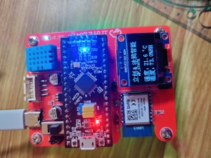
STM32F1 (using Yefire STM32F103C8T6 core board) or STC8A (maybe most people don’t have Yefire core board, but related functions can also be achieved using STC8A)
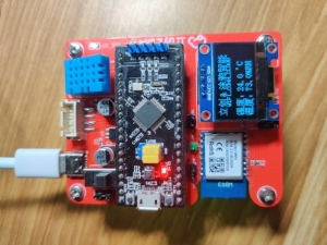
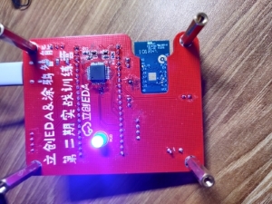
The reason why STC8A is placed on the back is that the order of RX and TX on the STM32 core board is reversed. Placing it on the back can facilitate wiring.
Select the MCU through the jumper cap (originally I wanted to do this so that when both MCUs have been programmed, the power can be disconnected without interfering with each other. Later I found that because the hardware IICs of the two MCUs were connected together, After STC8 burned the relevant IIC program, even if the STC8 was not powered, the STM32 program was still stuck in OLED initialization. In the end, it was solved by shielding the relevant code and then burning it into STC8, and when using STC8 , and cannot be inserted into the STM32 core board)
DHT11
Its precision humidity is ±5%RH, temperature is ±2℃, measuring range humidity is 5-95%RH, and temperature is -20~+60℃.
OLED_IIC or serial screen (reserved interface, not used)
The IIC bus is connected to the hardware IIC of the MCU
TUYA-WBR3
I have used ESP8266 to upload data to OneNET before. In comparison, the Tuya module is easier to use, and Tuya Smart provides MCU_SDK, which allows us to quickly complete MCU program development.
The three-color cycle changes to increase the presence of this small object.
Set thresholds for temperature and humidity and provide alarm function
The alarm function can be canceled by unplugging the jumper cap
When using the STM32 core board, since there are related circuits on the core board, disconnect it at this time. When selecting the MCU as STC, since the operating voltage of some devices is 3V3, it can provide a voltage source for the peripheral circuits at this time.
The schematic diagram of the two buttons on the PCB refers to the schematic diagram of the buttons on the Yefire STM32F103C8T6 core board. Capacitors are connected in parallel for hardware debounce, so there is no need for software debounce in the button processing function.
Github: https://github.com/Lin-Chengqiu/LCEDA-TUYA-Demo
1. Obtain temperature and humidity data through DHT11 and print it through the serial port;
2. Get the WBR3 working status through mcu_get_wifi_work_state(), and print the WIFI working status through the serial port
3. If the working status of WBR3 is WIFI_CONN_CLOUD, upload the temperature and humidity data to Tuya Smart and compare the cloud data and local data to see if they are consistent.
4. Display temperature and humidity data and WBR3 working status through OLED
5. Provide an alarm function through an active buzzer (at the beginning, I wanted to use RGB_LED to provide the alarm function, and then use it purely as an ambient light)
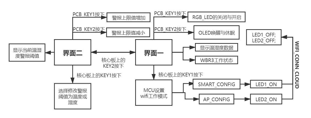
6. Plan the button functions, use buttons to turn off and on the RGB_LED, OLED wake-up and sleep, OLED interface switching, change the temperature and humidity alarm threshold, and write it into the FLASH of STM32, which can be saved after power-off and set the wifi working mode... ..
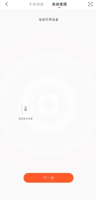
Network configuration is required when connecting the device for the first time.
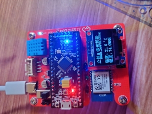
At this time, available devices can be found on the APP
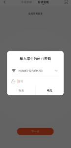
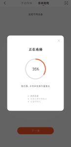
 int main()
 {
   All_init();
   while (1)
   {
     wifi_uart_service();
     alarmBeep();
     getValue_and_update();
     KeyFunction();
     switch(screenMode)
     {
       case 0:screen0();break;
       case 1:screen1();break;
       default:break;
     }
   }
}I wrote the STM32 code first, and then directly transplanted part of the STM32 code to STC8. In fact, there is not much difference.
 int main()
 {
   All_init();
   while (1)
   {
     wifi_uart_service();
     getValue_and_update();
     KeyScan();
     screen();
   }
 }
All reference designs on this site are sourced from major semiconductor manufacturers or collected online for learning and research. The copyright belongs to the semiconductor manufacturer or the original author. If you believe that the reference design of this site infringes upon your relevant rights and interests, please send us a rights notice. As a neutral platform service provider, we will take measures to delete the relevant content in accordance with relevant laws after receiving the relevant notice from the rights holder. Please send relevant notifications to email: bbs_service@eeworld.com.cn.
It is your responsibility to test the circuit yourself and determine its suitability for you. EEWorld will not be liable for direct, indirect, special, incidental, consequential or punitive damages arising from any cause or anything connected to any reference design used.
Supported by EEWorld Datasheet