1 System Design
Figure 1 is a schematic diagram of the shunt capacitor static compensator (SVC) system principle. The detection controller part is the core module of the system. This module is composed of 80C196KC MCU, voltage and current signal conditioning circuit, output alarm, control output circuit, and expanded program and data memory for 80C196KC work. 80C196KC is a 16-bit microcontroller with high running speed, fast data processing and strong interrupt function. In addition, the 80C196KC comes with 8-channel 10-bit A/D converters, whose resolution and accuracy are sufficient to meet the accuracy requirements of industrial control.

The three-phase voltage and current signals are sent to the detection controller through the voltage and current transformer module, and enter the A/D conversion channel of 80C196KC through the signal conditioning circuit. Six channels in the A/D conversion channel are used for three-phase voltage and current. Detection, one channel is used to detect the status of the neutral line and monitor the three-phase balance of the power grid.
80C196KC processes the quantified voltage and current signals to obtain the peak value, effective value, power and power factor of each phase of the power grid, and then decides whether to switch on, switch off or alarm the capacitor, and realizes capacitor switch on and off through the capacitor switch actuator. Throw and cut. The capacitor switching and switching actuator module is responsible for switching on and off the compensation capacitor at the voltage zero-crossing point to reduce the impact of switching and switching capacitors on the power grid and ensure the safety of the system capacitor bank.
2 Implementation of system functions
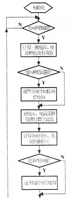
The workflow of realizing system functions is shown in Figure 2. After initialization, 80C196KC starts to periodically sample the 7 A/D channels. The implementation principle is as follows: Use the HSO of 80C196KC to trigger the T2 (timer 2) reset event, which generates a soft timer interrupt. In the interrupt service program, A/D conversion is started channel by channel, and the A/D sampling result is stored. into the array (the flow chart of HSO triggering scheduled interrupt is omitted). After completing a set of data that can be processed by the 80C196K CMCU, the sampling data completion flag is set, and then the next round of data sampling is performed.
The sampling data must be able to meet the needs of 80C196KC for time domain and frequency domain analysis of the monitored signal. This includes the detection of voltage peaks, calculation of the effective values of each phase voltage and current, and calculation of the phase difference between the voltage and current of each phase, thereby calculating the reactive power of each phase of alternating current, and analyzing the harmonic spectrum of each phase voltage and current. Analysis etc. The design requires that the content of harmonics below the 15th order can be analyzed. According to the Nyquist sampling theorem, the sampling frequency must be greater than twice the highest frequency of the signal spectrum (Ωs>2Ωh), and twice the frequency of the 15th harmonic is 1.5kHz; considering that the base-2 FFT algorithm is used and 32 points are sampled in each AC signal cycle, then:
The 
requirements of the sampling theorem are met. The second issue is the number of samples. In order to improve the resolution of spectral lines, the longer the array length for DFT, the better, but this comes at the expense of a long time. Considering the time factor, the array length of DFT is set at 256 (8 fundamental wave periods). The 80C196KC operating at 20MHz takes about 1.3s to perform a DFT, which can achieve high-precision signal spectrum analysis. Finally, the A/D sampling interval must be accurate enough, which requires the HSO to trigger a scheduled interrupt cycle that is not affected by other interrupts. The following technology is used to implement it: for each interrupt source higher than HSO in the program, there is an entry interrupt flag bit in the interrupt service routine. When starting a sampling cycle, these interrupt flag bits are cleared; during the sampling cycle, if the MCU finds that the interrupt flag bit is not zero, it discards the collected data and immediately restarts a new sampling cycle. At the same time, during the sampling period of the seven sampling channels, all maskable interrupts are turned off (query mode is available for A/D sampling, but A/D interrupts cannot be turned off if interrupt mode is used) to ensure the consistency of the sampling interval. Theory and practice have proven that sampling the entire cycle of the signal can minimize the calculation error caused by the window effect in the transformation operation.
The peak value and effective value can be calculated using 32 points (1 cycle data) randomly selected from the sampling array. The effective value is calculated as:


Next, find the phase difference between the voltage and current of each phase. Here, the method of solving the phase difference of the fundamental wave is used to eliminate the influence of harmonics on the calculation. Since the sampling signal contains harmonic components, the sampling array must first be digitally filtered, and then the cyclic cross-correlation calculation of each phase voltage and current must be performed to obtain the phase difference between the two. A 6th order IIR Chebyshev digital filter is used, the cutoff frequency is set to 60Hz, and the filter is designed using Labview. Since the IIR digital filter is a digital filter based on an infinitely long sequence, to achieve the ideal filtering effect, the sequence must be of sufficient length. Through simulation, when the sequence length is 96 (points), after extracting 32 points as the filtering results, and then performing cross-correlation calculations, the accuracy of the phase difference between the voltage and current can meet the design requirements. The principle of using the cross-correlation method to calculate the phase difference of two sinusoidal signals is:
assuming that both signals are sinusoidal functions and have the same frequency; the phase difference is

where n1 and n2 are signal noise. Since signal and noise, noise and noise are independent of each other, the calculation result of equation (1) is:

equation (2) shows that: for two signals with the same phase frequency, the cross-correlation function is cosine with the phase difference between the two signals. relation. According to the above analysis, in practice, the cyclic cross-correlation operation of 32-point voltage and current signals is used. The algorithm is:
After 
each step of cross-correlation operation between sequence y and sequence x, move the number at the beginning of the column to the end of the column, and then perform The next step is cross-correlation operation until k reaches N-1. In order to speed up the operation, according to the nature of the cross-correlation function, the specific steps are as follows:
① Determine the voltage array sequence, shift the current array sequence and perform cross-correlation operations with the voltage sequence. Each calculation step is performed with the operation value of the previous step. By comparison, if the change trend of the operation value is from small to large, and then from large to small, the phase difference between the voltage and current can be calculated based on the number of steps of the current sequence shift at the maximum point. In this case the current is lagging (inductive load). Assume that the two sequences obtain the maximum value in the k-th step of the cross-correlation operation, then the phase difference between the voltage and the current is:

② If k exceeds 8 (N/4) and the cross-correlation operation still does not obtain the maximum value, the cross-correlation should be found in the opposite direction Calculate the maximum value (because the phase difference cannot reach π/2). At this time, the current array sequence is determined, the voltage array sequence is shifted and cross-correlated with the current sequence. In this case, the operation result is advanced (capacitive load).
③ If the maximum value of the cross-correlation operation cannot be found after the two steps ① and ②, it is necessary to perform piecewise parabolic interpolation at the zero point of the phase difference to determine the phase difference between the two signals. See ④ for the processing principle and method.
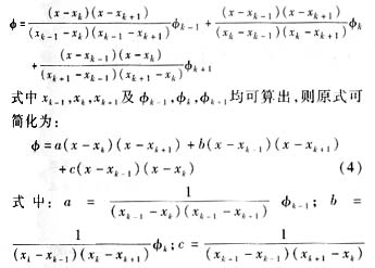
④ Resolution problem of phase difference: The resolution of the phase difference calculated by equation (3) is or 0.19635 (radians) = 11.25 (degrees). This resolution is extremely low and far from meeting the design accuracy requirements. The angle resolution can be improved by increasing the number of sampling points of the periodic signal, but it is limited by the A/D sampling speed. A feasible method is to use piecewise interpolation method. Since the cross-correlation function has a cosine relationship with the phase difference between the two signals and is very close to a parabola near the maximum value, the best effect can be achieved by using the piecewise parabolic interpolation method. The specific method is:
take three points xk-1, xk, xk+1, and the cross-correlation operation obtains the maximum value at point xk, and perform interpolation according to the following formula:

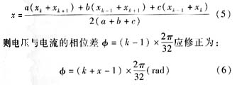
φk+1 Derive the equation (4) and let φ′=0 , solve for the offset of the interpolation point of the phase difference:
After 
performing digital filtering on 96 sampling points, use Equation (6) to interpolate the cross-correlation results. The accuracy of the calculated phase difference between the two signals is about 0.1°, which satisfies Design accuracy requirements.
According to equation (6), the capacitance or inductance of each phase of the power grid can be determined, and the switching and cutting directions of the compensation capacitor can be determined; combined with the calculation formulas of the effective values of voltage and current, the switching and cutting amounts of the compensation capacitor can be determined.
The total harmonic voltage distortion rate of the system is defined as:

Um in equation (7) is the root mean square value of each harmonic voltage component, and U1 is the root mean square value of the fundamental voltage. In the same way, the total harmonic current distortion rate can be obtained. National standards stipulate that the total harmonic voltage distortion (THD) of low-voltage power grids (<1kV) is less than 5%.
After the controller completes the reactive power detection and calculation, it extracts the base-2 FFT algorithm "in steps" according to time to transform the voltage and current of each phase, obtains the fundamental wave and each harmonic component value, and then calculates the total harmonic voltage , current distortion rate, determine whether to alarm or switch on or off the compensation capacitor according to the upper limit.
The so-called "fractional" means that each time the controller performs a three-phase reactive power calculation cycle, it only performs DFT transformation on one phase voltage or current, that is, it takes 6 working cycles to complete a complete harmonic spectrum analysis. The purpose is to improve The system judges reactive power faster and compensates for the power factor faster.
3 Summary:
The reactive power detection controller based on 80C196KC MCU uses the theory of digital signal processing to technically realize digital filtering, phase difference calculation and harmonic spectrum analysis. This detection controller has passed trial operation and has achieved good results, meeting the design requirements in terms of function and accuracy. For situations where power grid fluctuations are not too severe, the control effect is satisfactory. In order to track and compensate for the reactive power components of the power grid faster, DSP chips can be considered to increase the processing speed. In order to obtain the correlation characteristics between each signal, a high-speed, high-precision, multi-channel synchronous sampling A/D converter can be used to further improve the compensation effect.
references
[1] Jin Longzhang, Ding Yushan. Practical technology of reactive power compensation in power grid [M]. Beijing: China Water and Hydropower Press, 2001.
Previous article:Application of digital signal processing technology in reactive power compensation of power grid
Next article:Full digital modulator design with RF output
Recommended ReadingLatest update time:2024-11-16 17:38


- Popular Resources
- Popular amplifiers
-
 Microgrid Stability Analysis and Control Microgrid Modeling Stability Analysis and Control to Improve Power Distribution and Power Flow Control (
 -
 Modern Electronic Technology Training Course (Edited by Yao Youfeng)
 -
 New Energy Vehicle Control System Inspection and Maintenance (Edited by Bao Pili)
 -
 Intelligent Control Technology of Permanent Magnet Synchronous Motor (Written by Wang Jun)
- Huawei's Strategic Department Director Gai Gang: The cumulative installed base of open source Euler operating system exceeds 10 million sets
- Analysis of the application of several common contact parts in high-voltage connectors of new energy vehicles
- Wiring harness durability test and contact voltage drop test method
- Sn-doped CuO nanostructure-based ethanol gas sensor for real-time drunk driving detection in vehicles
- Design considerations for automotive battery wiring harness
- Do you know all the various motors commonly used in automotive electronics?
- What are the functions of the Internet of Vehicles? What are the uses and benefits of the Internet of Vehicles?
- Power Inverter - A critical safety system for electric vehicles
- Analysis of the information security mechanism of AUTOSAR, the automotive embedded software framework
 Professor at Beihang University, dedicated to promoting microcontrollers and embedded systems for over 20 years.
- Innolux's intelligent steer-by-wire solution makes cars smarter and safer
- 8051 MCU - Parity Check
- How to efficiently balance the sensitivity of tactile sensing interfaces
- What should I do if the servo motor shakes? What causes the servo motor to shake quickly?
- 【Brushless Motor】Analysis of three-phase BLDC motor and sharing of two popular development boards
- Midea Industrial Technology's subsidiaries Clou Electronics and Hekang New Energy jointly appeared at the Munich Battery Energy Storage Exhibition and Solar Energy Exhibition
- Guoxin Sichen | Application of ferroelectric memory PB85RS2MC in power battery management, with a capacity of 2M
- Analysis of common faults of frequency converter
- In a head-on competition with Qualcomm, what kind of cockpit products has Intel come up with?
- Dalian Rongke's all-vanadium liquid flow battery energy storage equipment industrialization project has entered the sprint stage before production
- Allegro MicroSystems Introduces Advanced Magnetic and Inductive Position Sensing Solutions at Electronica 2024
- Car key in the left hand, liveness detection radar in the right hand, UWB is imperative for cars!
- After a decade of rapid development, domestic CIS has entered the market
- Aegis Dagger Battery + Thor EM-i Super Hybrid, Geely New Energy has thrown out two "king bombs"
- A brief discussion on functional safety - fault, error, and failure
- In the smart car 2.0 cycle, these core industry chains are facing major opportunities!
- The United States and Japan are developing new batteries. CATL faces challenges? How should China's new energy battery industry respond?
- Murata launches high-precision 6-axis inertial sensor for automobiles
- Ford patents pre-charge alarm to help save costs and respond to emergencies
- New real-time microcontroller system from Texas Instruments enables smarter processing in automotive and industrial applications
- Push-button start system power supply circuit
- Tell us what you think about 996
- Amplification issues of differential amplifiers
- New design approach improves smart meter performance
- How to view NPU clock power configuration and information for Allwinner V853 chip?
- USB PD fast charging communication principle
- How to obtain CCS License from TI
- The semiconductor industry is facing a cold winter. What do you think?
- How do I control AO3401?
- It was found that the build script of micropython converts the .py file into a c file and then compiles it.

 Microgrid Stability Analysis and Control Microgrid Modeling Stability Analysis and Control to Improve Power Distribution and Power Flow Control (


 京公网安备 11010802033920号