With the rise and popularity of smartphones, people are becoming more and more dependent on their phones. However, due to the limitations of battery technology, the frequency of charging mobile phones has also decreased dramatically as their functions have expanded, from once every two or three days to once a day or even less. The emergence of wireless charging technology has made the charging process more convenient and also solved the compatibility issues between different mobile phones. At present, the mainstream wireless charging technologies mainly include the following three categories:
Reference address of this article: http://www.eepw.com.cn/article/201809/388230.htm
1) Electromagnetic induction: A coil with oscillating circuit characteristics is used in each of the two devices to form a set of transceiver coils. When an alternating current of several megahertz is added to the coil of the transmitting device, an induced electromotive force will be generated on the coil of the receiving device, thereby realizing the wireless transmission of electric energy. At present, the transmission power of wireless charging technology based on electromagnetic induction ranges from a few watts to several hundred watts, and the transmission distance is less than 1 cm.
2) Radio waves: According to the principles of electromagnetism, when ultra-high frequency alternating current passes through a vertical conductor rod, electromagnetic waves will be formed around it. Within a specific frequency, we call this conductor rod emitting radio waves. If a circular coil is used as an antenna and placed in the periodically changing magnetic field of the radio wave, a corresponding current will be induced in the coil. Wireless charging technology based on radio waves utilizes the principle that radio wave energy can be sent and received through antennas, and directly converts the AC waveform of the radio wave into DC in the rectifier circuit for use. The transmission power of wireless charging technology based on radio waves is less than 100 milliwatts, and the transmission distance can reach up to 10 meters.
3) Electromagnetic resonance method: Energy can be effectively transmitted between two objects with the same resonant frequency, while the interaction between objects with different frequencies is weak. Based on this principle, the MIT research team used two copper coils as electromagnetic resonators in the light bulb experiment. One coil is connected to the power supply as a transmitter, and the other coil is connected to the light bulb as a receiver. After power is turned on, the transmitter can vibrate at a frequency of 10MHz, but it does not emit electromagnetic waves outward, but forms a strong non-radiative magnetic field around it. This non-radiative magnetic field can coordinate with the receiving coil for energy transmission. The transmission power of wireless charging technology based on electromagnetic resonance can reach several kilowatts, and the transmission distance can reach several meters.
This article uses TI's BQ500410A chip to form the TX end of the wireless charging system, and TI's BQ51013B is used on the RX end. This solution uses 3 transmitting coil arrays to expand position freedom, and has the functions of parasitic metal detection (PMOD) and foreign object detection (FOD) to ensure the safety of the charging process.
1. Principle Introduction
1.1 Transmission Principle
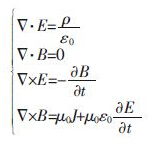
Wireless charging technology based on electromagnetic induction is similar to transformers, and is based on the principle of electromagnetic induction. Classical electromagnetism can be summarized as a set of famous Maxwell equations, namely:

From the above Maxwell equations, we can see that a changing electric field will produce a changing magnetic field, and a changing magnetic field will also produce a changing electric field. This process repeats and forms an electromagnetic field. With one wavelength as the boundary, within a wavelength range centered on the field source, it becomes a near field, also known as an induction field; beyond a wavelength range, it becomes a far field, also known as a radiation field. The electromagnetic field intensity in the induction field is large, but it decays quickly; on the contrary, the electromagnetic field intensity in the radiation field is small, but it decays slowly.
Wireless charging technology based on electromagnetic induction applies this principle. The transmitter uses inverter technology to convert the rectified DC power from the power grid into high-frequency AC power, so an alternating magnetic field is generated around the transmitting coil. The receiving coil located in the induction field generates an induced electromotive force due to electromagnetic induction, which is then rectified and shaped for use by the load.
1.2 System Structure
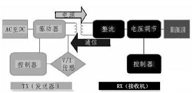
A complete wireless charging system consists of two parts: the TX end and the RX end, and its structural block diagram is shown in Figure 1.
The structure of wireless charging is similar to that of an air-core transformer, and energy transmission is achieved through coil coupling. Usually, the transmitting coil and its driving circuit are installed in a charging plate, and the receiving coil and its driving circuit are embedded in the device to be charged, such as a smartphone. The efficiency of energy transmission is related to factors such as the distance between coils, the degree of coil alignment, coil direction, coil material, magnetic field shielding, impedance matching, transmission frequency and duty cycle. Among them, the distance and alignment between coils have a great influence on the transmission efficiency.

Figure 1 Wireless charging system block diagram
This article uses an array of three transmitting coils to expand the charging area in order to obtain better charging efficiency and experience. The BQ500410A enables the three transmitting coils in turn at a time interval of 400ms, and enables the analog switch of the corresponding COMM feedback signal path at the same time. The BQ500410A will look for the strongest COMM feedback signal, and then drive the corresponding transmitting coil to work to obtain the best coil matching. Therefore, only one transmitting coil is working at the same time, and the other two transmitting coils are in standby mode.
In order to reduce electromagnetic radiation, the wireless charging system also adds a ferrite magnetic isolation sheet on the back of the coils at both ends of the transmitter and receiver, so that the energy transmission area is limited to between the two magnetic isolation sheets, avoiding the radiation generated by the wireless charging system when working to interfere with smartphones or other devices.
1.3 FOD and PMOD
Foreign object detection (FOD) and parasitic metal detection (PMOD) are another major feature of the design in this article. Metal objects in an AC magnetic field will generate eddy currents. Therefore, for safety reasons, it is necessary to detect in real time whether there are foreign objects and parasitic metals between the TX and RX ends. When the system is working, BQ500410A monitors the input voltage and input current in real time and calculates the input power. At the same time, BQ51013B also monitors the charging voltage and charging current in real time, and feeds back the output power to BQ50041A through the communication protocol. BQ50041A can configure the loss threshold through resistors. If the difference between the input power and the output power is greater than this loss threshold, BQ50041A will alarm and terminate energy transmission.
1.4 Low Power Consumption
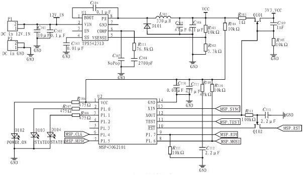
This article achieves low power consumption of the system by adding TI's MSP430 low-power MCU to cooperate with BQ500410A. In order to achieve low power consumption, one of the most direct methods is to directly turn off the power supply when there is no load to completely shut down the BQ50041A. However, if this is done, the charging status, error status, operation mode and drive pin status information will be completely lost. After adding MSP430, BQ500410A can be shut down periodically to save power consumption, and its wake-up signal is provided by MSP430. At the same time, various status information is also saved by MSP430, and the LED status indicator is also driven by MSP430 instead of the original BQ500410A. In this way, although the complexity and cost of the system are increased, the standby power consumption is reduced from the original 300mW to about 90mW.

Figure 2 Low power circuit
2. Conclusion
The wireless charging system proposed in this paper solves the problem of small charging area of the traditional single-coil solution, greatly improving the user experience. Therefore, the solution in this paper has higher market value. In addition, the low-power circuit added in this paper can reduce the standby power consumption from 300mW to 90mW, which can better meet the needs of some low-power devices.
Previous article:WiFi Antenna Design and Optimization Based on ANSYS HFSS Software
Next article:A brief analysis of the impact of RF passive components on wireless communications
- Huawei's Strategic Department Director Gai Gang: The cumulative installed base of open source Euler operating system exceeds 10 million sets
- Analysis of the application of several common contact parts in high-voltage connectors of new energy vehicles
- Wiring harness durability test and contact voltage drop test method
- Sn-doped CuO nanostructure-based ethanol gas sensor for real-time drunk driving detection in vehicles
- Design considerations for automotive battery wiring harness
- Do you know all the various motors commonly used in automotive electronics?
- What are the functions of the Internet of Vehicles? What are the uses and benefits of the Internet of Vehicles?
- Power Inverter - A critical safety system for electric vehicles
- Analysis of the information security mechanism of AUTOSAR, the automotive embedded software framework
 Professor at Beihang University, dedicated to promoting microcontrollers and embedded systems for over 20 years.
- Innolux's intelligent steer-by-wire solution makes cars smarter and safer
- 8051 MCU - Parity Check
- How to efficiently balance the sensitivity of tactile sensing interfaces
- What should I do if the servo motor shakes? What causes the servo motor to shake quickly?
- 【Brushless Motor】Analysis of three-phase BLDC motor and sharing of two popular development boards
- Midea Industrial Technology's subsidiaries Clou Electronics and Hekang New Energy jointly appeared at the Munich Battery Energy Storage Exhibition and Solar Energy Exhibition
- Guoxin Sichen | Application of ferroelectric memory PB85RS2MC in power battery management, with a capacity of 2M
- Analysis of common faults of frequency converter
- In a head-on competition with Qualcomm, what kind of cockpit products has Intel come up with?
- Dalian Rongke's all-vanadium liquid flow battery energy storage equipment industrialization project has entered the sprint stage before production
- Allegro MicroSystems Introduces Advanced Magnetic and Inductive Position Sensing Solutions at Electronica 2024
- Car key in the left hand, liveness detection radar in the right hand, UWB is imperative for cars!
- After a decade of rapid development, domestic CIS has entered the market
- Aegis Dagger Battery + Thor EM-i Super Hybrid, Geely New Energy has thrown out two "king bombs"
- A brief discussion on functional safety - fault, error, and failure
- In the smart car 2.0 cycle, these core industry chains are facing major opportunities!
- The United States and Japan are developing new batteries. CATL faces challenges? How should China's new energy battery industry respond?
- Murata launches high-precision 6-axis inertial sensor for automobiles
- Ford patents pre-charge alarm to help save costs and respond to emergencies
- New real-time microcontroller system from Texas Instruments enables smarter processing in automotive and industrial applications
- Share: BQ24040: BQ2404X Series Device Schematic and Layout Review
- I searched for information and saw a genius who spent three months making a super mini TV.
- Looking to buy a complete set of information on scooter controller
- EEWORLD University Hall----Live Replay: Microchip Security Series 8 Platform Firmware Security Resilience
- The power solution for high-efficiency SiC FET is here, come and take a look.
- NPN transistor saturation conduction conditions VB>VC, VB>VE
- [Top Micro Intelligent Display Module Evaluation] 3. Create and download a project
- Overcome pain points and win gifts | Tektronix's full range of oscilloscopes can help you solve your problems!
- STM32MP157A-DK1 Review + Camera (3)
- [RVB2601 Creative Application Development] Zero-based Part 1: Play with RVB2601 (based on RISC-V MCU) Getting Started Board Power On

 Wireless Magnetic Charging Paper


 京公网安备 11010802033920号