1. Basic principles
A stepper motor is an actuator that is controlled by electric pulses and converts electric pulses (digital signals) into angular displacement.

Usually the rotor of a stepper motor is a permanent magnet. When current flows through the stator winding, the stator winding generates a vector magnetic field. This magnetic field drives the rotor to rotate an angle, so that the direction of a pair of magnetic fields of the rotor is consistent with the direction of the magnetic field of the stator. When the vector magnetic field of the stator rotates an angle, the rotor also rotates an angle with the magnetic field. When the stepper driver receives a pulse signal, it drives the stepper motor to rotate a fixed angle (called "step angle") in the set direction. Its rotation is run step by step at a fixed angle.
The angular displacement output by the stepper motor is proportional to the number of input pulses, and the speed is proportional to the pulse frequency. If the order in which the windings are energized is changed, the motor will reverse. Therefore:
The angular displacement can be controlled by controlling the number of pulses, thereby achieving accurate positioning;
The speed and acceleration of the motor can be controlled by controlling the pulse frequency, thus achieving the purpose of speed regulation;
The purpose of controlling the forward and reverse rotation of the motor can be achieved by controlling the order in which the windings are energized.
Stepper motors can be used as a special motor for control. Taking advantage of their characteristic of no accumulated error, they are widely used in various open-loop controls.
2. Stepper Motor Classification
2.1 Classification by stator phase number
There are x windings for x phases.
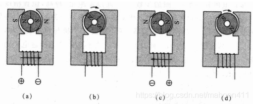
2.1.1 Single-phase stepper motor
The electromagnetic torque of a single-phase stepper motor is only generated when the stator current changes. Its average torque is much smaller than that of a motor with more than two phases, and its response pulse frequency is also below 100pps (pulse per second). Therefore, its use is greatly limited and it can only operate under light loads with relatively low response pulse frequencies, such as clocks, car timers, and water meter counters.
2.1.2 Two-phase stepper motor
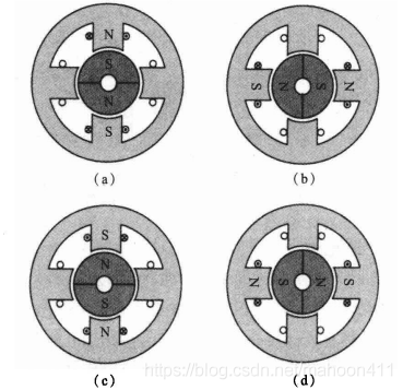
As shown in the figure above, the number of stator poles is 4, which is equivalent to one winding occupying two poles.

As shown in the figure above, the number of stator poles is 8, which is equivalent to one winding occupying four poles.
2.1.3 Three-phase stepper motor

The number of main poles of the stator coil of a three-phase stepper motor is a multiple of three, so the number of main poles of the stator of a three-phase stepper motor is 3, 6, 9, 12, etc.
2.1.4 Four-phase stepper motor
The driver structure of the four-phase stepper motor is complex and expensive, and is only used for special purposes.
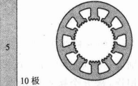
2.1.5 Five-phase stepper motor
2.2 Classification by rotor structure
2.2.1 Permanent Magnet Stepper Motor (PM)
The rotor is made of permanent magnetic material. The PM type rotor is an inner rotor type, with N and S poles distributed on the outer surface of the cylindrical rotor (without teeth on the outer surface).
Single-phase permanent magnet stepper motor

Two-phase permanent magnet stepper motor

Features: Permanent magnet stepper motor has large output torque and good dynamic performance, but large step angle.
2.2.2 Variable Reluctance (VR) Stepper Motor
The rotor is made of magnetic conductors such as silicon steel sheets or electrical pure iron rods, and the outer surface of the rotor is a multi-tooth structure (the teeth of the rotor produce changes in magnetic resistance when it rotates, so it is also called a variable reluctance motor).
When the stator coil is energized, the stator poles become magnetized, attracting the rotor teeth and generating torque, causing it to move one step.
Compared to permanent magnet motors, which produce both magnetic attraction and repulsion torques, reactive stepper motors produce only attraction torque.
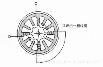
The figure below shows the structure of a reactive stepper motor. In the figure, 12 magnetic poles are evenly distributed on the stator, and each magnetic pole is 30° apart; four coils with a 90° difference form a single-phase winding. The number of rotor teeth is 8. When a single-phase winding is energized, its stator pole attracts the rotor teeth, minimizing the air gap magnetic resistance and reaching a stationary position.
Next, let’s explain how it works:
The first step is a simplified diagram of the first phase coil. The cross-section line indicates that the first phase stator is excited, the rotor is attracted by the first phase stator pole, and the rotor teeth are turned under the stator pole.
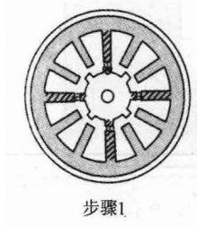
In the second step, the current of the first phase winding is turned off, and the second phase winding is energized. The rotor rotates counterclockwise one step (15° = tooth pitch divided by the number of stator phases) and stops under the second phase stator pole.

In the third step, the third phase winding is energized, and the rotor rotates 15° counterclockwise and stops relative to the third phase magnetic pole of the stator.
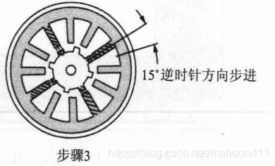
The next moment, the first phase winding is energized again, and the rotor position in step 3 rotates 15° counterclockwise to under the first phase stator pole, returning to the first step state.
Features: simple structure, low production cost, small step angle. However, because the reactive stepper motor does not use permanent magnets, the magnetic field strength of its stator and rotor is proportional to the excitation current. In order to increase the magnetic field strength, a large excitation current is required, so the temperature rise is very high, the heat sink is also large, and the dynamic performance is poor, the efficiency is low, and the reliability is poor.
2.2.3 Hybrid Stepping (HS)
Hybrid stepper motors are available in two-phase, three-phase, and five-phase types. This section will explain the two-phase hybrid stepper motor.
The name of the hybrid stepper motor comes from its rotor structure, which is a combination of a PM rotor and a VR rotor.
The rotor structure of the hybrid stepper motor is composed of two magnetic discs with a permanent magnet cylinder sandwiched in the middle, which are axially strung together. The outer circular teeth of the two magnetic discs have the same pitch, which is the same as the aforementioned VR type rotor structure. The teeth of the two discs are installed with a 1/2 pitch staggered. The rotor cylindrical permanent magnet is axially magnetized, with one end being N and the other end being S.

This type of motor rotor is similar to the PM type rotor described above in structure. The N pole and S pole of the PM type rotor are distributed on the outer surface of the rotor. To improve the resolution, the number of pole pairs must be increased. Usually, a rotor with a diameter of 20mm can be configured with 24 poles. If the number of poles is increased, the leakage magnetic flux will increase and the electromagnetic torque will be reduced. The N pole and S pole of the rotor of the hybrid stepper motor are distributed on two different soft magnetic disks. Therefore, the number of rotor poles can be increased, thereby improving the resolution. A rotor with a diameter of 20mm can be configured with 100 poles, and the magnetization direction of the magnetic pole is axial. The N pole and S pole are magnetized after assembly, and magnetization is simple.
The stator poles corresponding to the rotor teeth have small teeth on the inner diameter of the main poles with the same pitch as the rotor teeth. They interact with the magnetic flux of the rotor teeth in the air gap and can generate electromagnetic torque.
The figure below shows the magnetic circuit of a two-phase hybrid stepper motor.

The figure below is the working principle diagram of a two-phase hybrid stepper motor.

Next, we will use a physical model to explain in detail the working principle of the hybrid stepper motor.
The picture below is a bipolar four-wire two-phase hybrid stepper motor.
Note: You don’t need to worry about what bipolar is here, just read on.
Note: "Four-wire" means that the stepper motor has four connection ports.

The figure below shows the rotor structure of the above-mentioned stepper motor.

The inside of the rotor is shown in the figure below. As can be seen from the figure, it is composed of permanent magnets and gear caps.

The gear cap itself is not magnetic, but when it comes into contact with a permanent magnet, it becomes magnetic.

After looking at the rotor, let's analyze the stator. The rotor has 50 teeth, and the stator has only 48 teeth.


From the picture below, you can see that it actually has only two independently energized coils, which means that this stepper motor is a two-phase stepper motor.
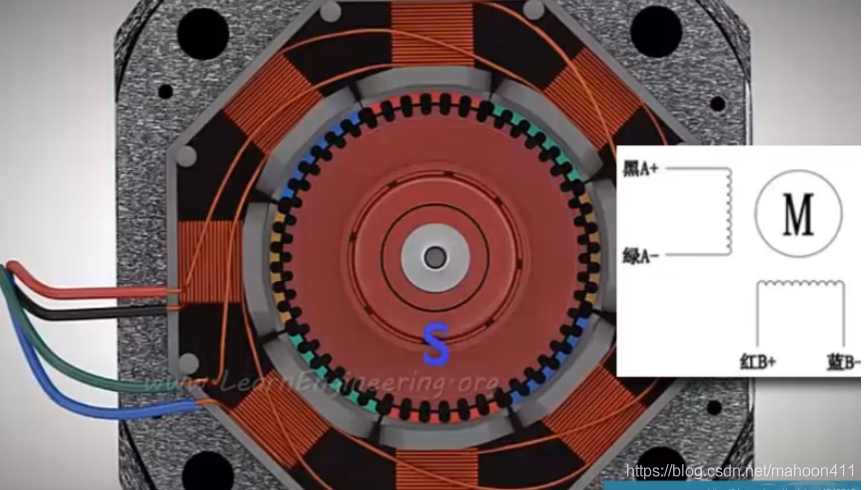
We identify the two coils as A and B, as shown below:
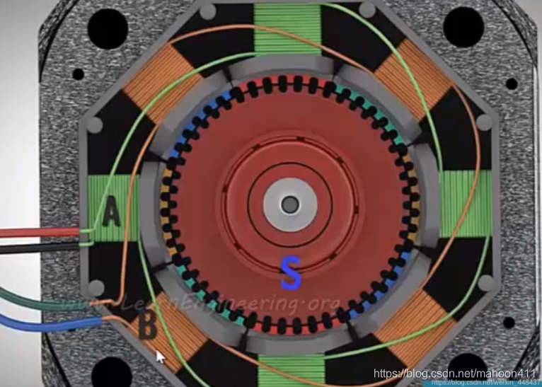
This is to energize coil A, as shown in the figure below: the rotor tooth is the S pole, the coil will generate a magnetic field, and since opposites attract, the red stator teeth will be attracted to the rotor teeth, and since likes repel, the yellow teeth will repel the rotor teeth.
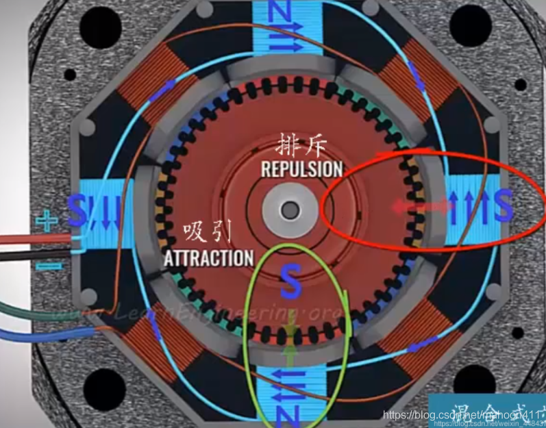
When coil A is powered off and coil B is powered on, the following figure is shown:
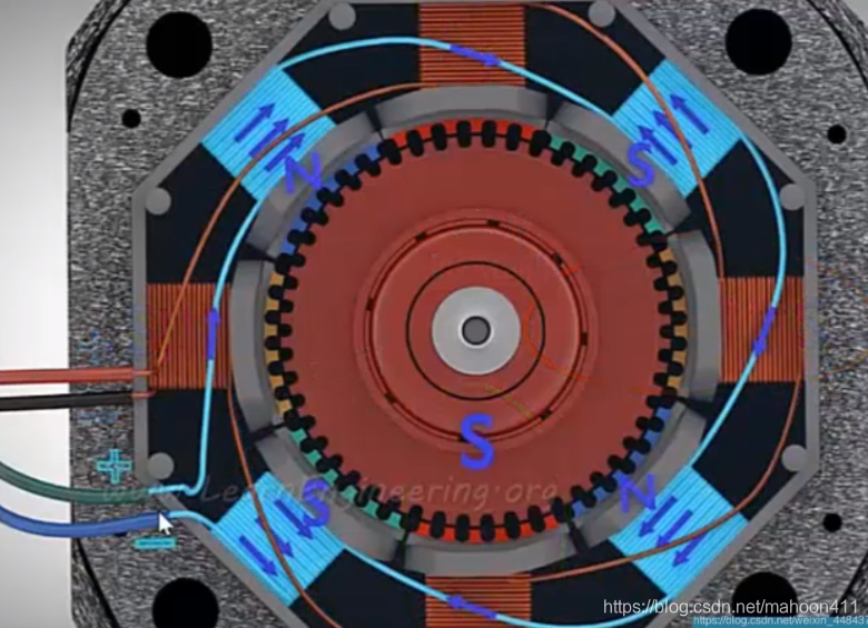
The magnetic field changes, and the stator will rotate slightly, by 1.8 degrees, as shown in the figure below: The rotor teeth are the S pole, and the coil will generate a magnetic field. Since opposite poles attract, the blue stator teeth will be attracted to the rotor teeth, and since like poles repel, the green teeth will repel the rotor teeth.

It is worth noting that this is a half-step drive mode, one step is 1.8 degrees, if both coils are energized at the same time, it is a full-step drive mode, one step is 0.9 degrees. This makes the control more precise.
Previous article:Motor windings: Symmetrical conditions for several different forms of fractional slot windings
Next article:Device selection in frequency converter
- Popular Resources
- Popular amplifiers
- Huawei's Strategic Department Director Gai Gang: The cumulative installed base of open source Euler operating system exceeds 10 million sets
- Analysis of the application of several common contact parts in high-voltage connectors of new energy vehicles
- Wiring harness durability test and contact voltage drop test method
- Sn-doped CuO nanostructure-based ethanol gas sensor for real-time drunk driving detection in vehicles
- Design considerations for automotive battery wiring harness
- Do you know all the various motors commonly used in automotive electronics?
- What are the functions of the Internet of Vehicles? What are the uses and benefits of the Internet of Vehicles?
- Power Inverter - A critical safety system for electric vehicles
- Analysis of the information security mechanism of AUTOSAR, the automotive embedded software framework
 Professor at Beihang University, dedicated to promoting microcontrollers and embedded systems for over 20 years.
- Innolux's intelligent steer-by-wire solution makes cars smarter and safer
- 8051 MCU - Parity Check
- How to efficiently balance the sensitivity of tactile sensing interfaces
- What should I do if the servo motor shakes? What causes the servo motor to shake quickly?
- 【Brushless Motor】Analysis of three-phase BLDC motor and sharing of two popular development boards
- Midea Industrial Technology's subsidiaries Clou Electronics and Hekang New Energy jointly appeared at the Munich Battery Energy Storage Exhibition and Solar Energy Exhibition
- Guoxin Sichen | Application of ferroelectric memory PB85RS2MC in power battery management, with a capacity of 2M
- Analysis of common faults of frequency converter
- In a head-on competition with Qualcomm, what kind of cockpit products has Intel come up with?
- Dalian Rongke's all-vanadium liquid flow battery energy storage equipment industrialization project has entered the sprint stage before production
- Allegro MicroSystems Introduces Advanced Magnetic and Inductive Position Sensing Solutions at Electronica 2024
- Car key in the left hand, liveness detection radar in the right hand, UWB is imperative for cars!
- After a decade of rapid development, domestic CIS has entered the market
- Aegis Dagger Battery + Thor EM-i Super Hybrid, Geely New Energy has thrown out two "king bombs"
- A brief discussion on functional safety - fault, error, and failure
- In the smart car 2.0 cycle, these core industry chains are facing major opportunities!
- The United States and Japan are developing new batteries. CATL faces challenges? How should China's new energy battery industry respond?
- Murata launches high-precision 6-axis inertial sensor for automobiles
- Ford patents pre-charge alarm to help save costs and respond to emergencies
- New real-time microcontroller system from Texas Instruments enables smarter processing in automotive and industrial applications
- This week's highlights
- STM device I2C drives 0.96 OLED display
- How to choose between different chips in TI's Sub-1GHz product line?
- EEWORLD University ---- Motor Control
- Component packaging,
- 5 Key Considerations for IoT Devices
- NUCLEO_G431RB Review Add UART
- A must-read summary of drone principles (II) Major systems of drones
- CC2640R2: TI BLE OAD (OTA) protocol APP process and code interpretation on Android and iOS
- Transistor source, and the difference between NPN and PNP


 Digilent Vivado library
 Principles of Digital Communications (Gallagher)


 京公网安备 11010802033920号