What is a stepper motor?
A stepper motor is an open-loop control motor that converts electrical pulse signals into angular displacement or linear displacement, also known as a pulse motor. In the case of non-overload, the motor's speed and stop position depend only on the frequency and number of pulses of the pulse signal, and are not affected by load changes. When the stepper driver receives a pulse signal, it can drive the stepper motor to rotate a fixed angle in the set direction, called the "step angle".

The rotation of the stepper motor is performed step by step at a fixed angle. The angular displacement can be controlled by controlling the number of pulses to achieve accurate positioning. At the same time, the speed and acceleration of the motor can be controlled by controlling the pulse frequency to achieve speed regulation. Stepper motors are mostly used in external devices of digital computers, as well as printers, plotters, and disks.
02
Characteristics of stepper motors
The position and speed signals of the stepper motor are not fed back to the control system when it is working. If the position and speed signals of the motor are fed back to the control system when it is working, then it belongs to a servo motor. Compared with servo motors, the control of stepper motors is relatively simple, but it is not suitable for occasions with high precision requirements.

The advantages and disadvantages of stepper motors are very prominent. The advantages are simple control and high precision, while the disadvantages are noise, vibration and efficiency. It has no cumulative error, simple structure, easy use and maintenance, and low manufacturing cost. Stepper motors have a large ability to drive load inertia and are suitable for small and medium-sized machine tools and places where speed accuracy is not required. The disadvantages are low efficiency, high heat generation, and sometimes "out of step". The advantages and disadvantages are as follows.
advantage:
1. The motor operation is easy to control by inputting pulse signals to the motor;
2. No feedback circuit is required to return the position and speed information of the rotating axis (open loop control);
3. Greater reliability due to the absence of contact brushes.
shortcoming:
1. Pulse signal output circuit is required;
2. When control is inappropriate, synchronization loss may occur;
3. Heat is generated because current continues to flow after the rotating shaft stops.
03
Classification of stepper motors
Under the conditions of the same current and the same torque output, a unipolar stepper motor has twice as many coils as a bipolar stepper motor, is more expensive, and has a different control circuit structure. Currently, most popular stepper motors on the market are bipolar stepper motors.

Stepper motors are usually classified mainly according to the characteristics of the rotor and the stator winding. The classification of these two types will be described in detail below.
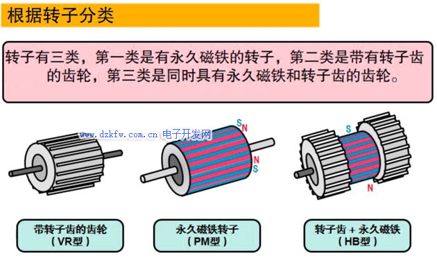
According to the rotor classification, there are three main types: reactive type (VR type), permanent magnet type (PM type), and hybrid type (HB type).
Reactive
There is a winding on the stator, which is made of soft magnetic material. It has a simple structure, low cost, and a small step angle, which can reach 1.2 degrees, but it has poor dynamic performance, low efficiency, high heat generation, and it is difficult to ensure reliability.
Permanent magnet
The rotor of the permanent magnet stepper motor is made of permanent magnet material, and the number of poles of the rotor is the same as that of the stator. It is characterized by good dynamic performance and large output torque, but this type of motor has poor speed and a large step angle (usually 7.5 degrees or 15 degrees).
Hybrid
The hybrid stepper motor combines the advantages of the reactive and permanent magnet types. It has many phase windings on the stator, and the rotor uses permanent magnet materials. Both the rotor and the stator have multiple small teeth to improve the step accuracy. It is characterized by large output torque, good dynamic performance, and small step angle, but the structure is complex and the cost is relatively high.
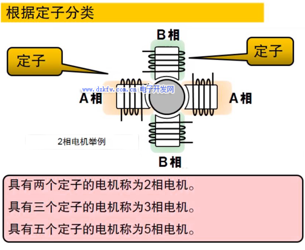
Stepper motors are classified according to the windings on the stator, and there are two-phase, three-phase and five-phase series. Currently, the most popular is the two-phase hybrid stepper motor, which accounts for more than 97% of the market share. The reason is that it is cost-effective and works well when equipped with a subdivided driver.
The basic step angle of this type of motor is 1.8 degrees/step. After being equipped with a half-step driver, the step angle is reduced to 0.9 degrees. After being equipped with a subdivision driver, the step angle can be subdivided up to 256 times (0.007 degrees/microstep). Due to friction and manufacturing precision, the actual control accuracy is slightly lower. The same stepper motor can be equipped with drivers of different subdivisions to change the accuracy effect.
04
Working Principle of Stepper Motor
The stepper motor is controlled by a pulse signal. Each time a pulse signal is input, the stepper motor moves forward one step. The step angle of the stepper motor is generated by proportional control based on the motor structure. If the subdivision control of the control circuit remains unchanged, the step angle of the stepper rotation is a fixed angle in theory. In actual work, the step angle of the motor rotation will have a slight difference, mainly due to the fixed error in the motor structure, and this error will not accumulate.
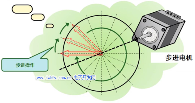
The greater the total number of poles of the stepper motor, the higher the processing accuracy requirement. Usually, the step angle of industrial hybrid stepper motors is 1.8 degrees, which means 200 poles.
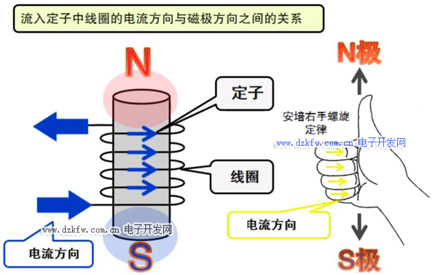
The phase current and magnetic field of the stepper motor follow Ampere's right-hand screw law. The magnetic field energy is generated by electrical energy. By controlling the motor phase current, the direction of the magnetic pole of the motor stator can be reversed. The changes in the two-phase magnetic field are coordinated, thereby generating the rotation of the motor.

If the direction of the current changes, the direction of the magnetic pole will also change. The process by which the current of the stepper motor flows through the stator to generate a magnetic field is called excitation.

The rotation of the motor rotor of the so-called two-phase stepper motor is achieved by the repulsion and attraction of magnetic fields of different magnetic poles. As shown in the figure above, the A phase generates an N-pole magnetic field to attract the S-pole of the rotor, and the B phase generates an S-pole magnetic field to attract the N-pole of the rotor, so that the stator generates a rotating force. If the current direction of the A and B phase stator coils is changed, the motor will produce another step of rotation. If the current direction of the A and B phase stator coils is continuously changed, the motor will produce continuous rotation.
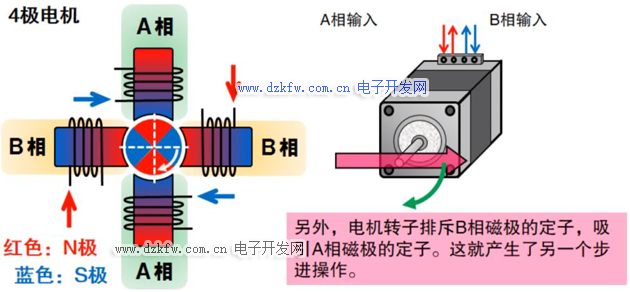
As shown in the figure above, the movement of the motor is achieved by changing the flow of current in the motor. The electronic rotor repels the stator of the B-phase magnetic pole and attracts the stator of the A-phase magnetic pole, which produces another stepping operation.
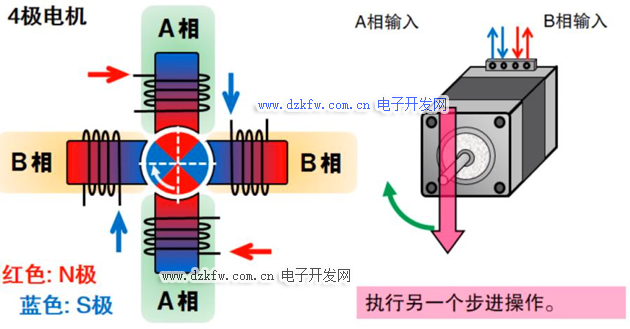
Perform another stepping operation, the motor stator pole is reversed, the rotor repels the stator with the B-phase pole and attracts the stator with the A-phase pole, as shown in the figure above.

As shown in the figure above, whenever the direction of the current in the stator coil changes, the magnetic pole will reverse and the rotor will repeat the stepping operation. Toshiba stepper motor drive control circuit controls the motor's magnetic field excitation through pulse width modulation, which can achieve efficient and stable operation of the motor.
05
Stepper Motor Operation Modes
The basic operation mode of a stepper motor is called the "excitation mode", which enables the stepper motor to operate in full-step mode, half-step mode, and micro-step mode. The micro-step mode can effectively reduce the noise of the stepper motor phase current and improve the inherent noise and vibration problems of the stepper motor. The following will introduce three excitation modes.
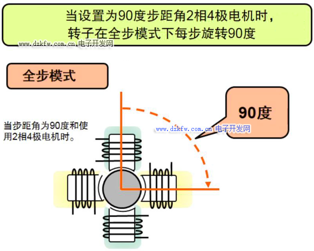
Full-step mode
The so-called full-step mode is to work at a fixed step angle according to the inherent structure of the motor. For one electric pulse, the stepper motor advances one step angle. This step angle is determined by the motor design structure, which can also be understood as the motor rotating at the maximum step angle.
Half-step mode
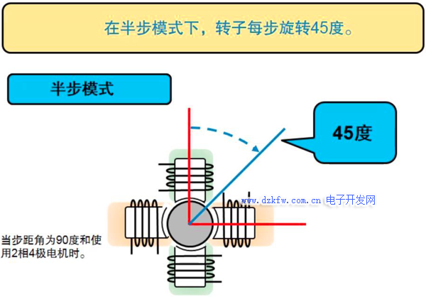
The half-step mode is to perform step rotation at half the step angle determined by the inherent structure of the motor. As shown in the figure below, the total number of poles of the stepper motor is 4, and the corresponding step angle is 90 degrees. In the half-step mode, the stepper motor rotates 45 degrees per pulse.
Microstep Mode
The microstep mode is similar to the half-step mode, with a smaller step angle, which is 1/4 step, 1/8 step, 1/16 step, and can be very finely divided. The corresponding step angle is the full step angle multiplied by the microstep coefficient.
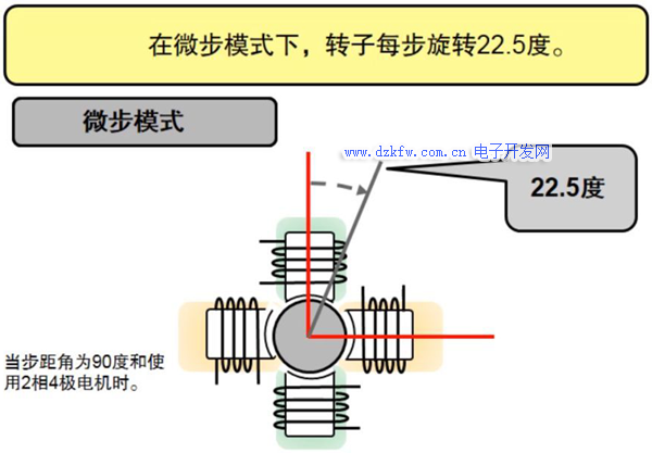
The smaller the step angle of the stepper motor, the higher the required processing accuracy will be, and the corresponding step angle error during microstepping will be greater.
06
Motor Control Drivers
The stepper motor cannot be directly connected to the industrial frequency AC or DC power supply, but must use a dedicated stepper motor driver, which consists of a pulse generation control unit, a power drive unit, a protection unit, etc. As shown in the figure below.
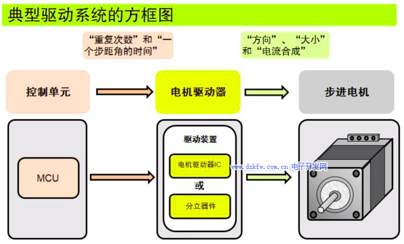
The drive unit is directly coupled to the stepper motor, which can also be understood as the power interface of the stepper motor microcomputer controller. The following example uses a system with MCU and discrete components. The MCU is equivalent to the brain that controls the motor. It sends the motor's step angle time, rotation direction, and number of repetitions to the discrete device. The discrete device will amplify the voltage and current based on the signal sent by the MCU and send it to the motor, thereby driving the motor to rotate.
Previous article:Introduction to four common ways of controlling motors with frequency converters
Next article:What is a servo motor? Common selection of servo motors
- Popular Resources
- Popular amplifiers
- Huawei's Strategic Department Director Gai Gang: The cumulative installed base of open source Euler operating system exceeds 10 million sets
- Analysis of the application of several common contact parts in high-voltage connectors of new energy vehicles
- Wiring harness durability test and contact voltage drop test method
- Sn-doped CuO nanostructure-based ethanol gas sensor for real-time drunk driving detection in vehicles
- Design considerations for automotive battery wiring harness
- Do you know all the various motors commonly used in automotive electronics?
- What are the functions of the Internet of Vehicles? What are the uses and benefits of the Internet of Vehicles?
- Power Inverter - A critical safety system for electric vehicles
- Analysis of the information security mechanism of AUTOSAR, the automotive embedded software framework
 Professor at Beihang University, dedicated to promoting microcontrollers and embedded systems for over 20 years.
- Innolux's intelligent steer-by-wire solution makes cars smarter and safer
- 8051 MCU - Parity Check
- How to efficiently balance the sensitivity of tactile sensing interfaces
- What should I do if the servo motor shakes? What causes the servo motor to shake quickly?
- 【Brushless Motor】Analysis of three-phase BLDC motor and sharing of two popular development boards
- Midea Industrial Technology's subsidiaries Clou Electronics and Hekang New Energy jointly appeared at the Munich Battery Energy Storage Exhibition and Solar Energy Exhibition
- Guoxin Sichen | Application of ferroelectric memory PB85RS2MC in power battery management, with a capacity of 2M
- Analysis of common faults of frequency converter
- In a head-on competition with Qualcomm, what kind of cockpit products has Intel come up with?
- Dalian Rongke's all-vanadium liquid flow battery energy storage equipment industrialization project has entered the sprint stage before production
- Allegro MicroSystems Introduces Advanced Magnetic and Inductive Position Sensing Solutions at Electronica 2024
- Car key in the left hand, liveness detection radar in the right hand, UWB is imperative for cars!
- After a decade of rapid development, domestic CIS has entered the market
- Aegis Dagger Battery + Thor EM-i Super Hybrid, Geely New Energy has thrown out two "king bombs"
- A brief discussion on functional safety - fault, error, and failure
- In the smart car 2.0 cycle, these core industry chains are facing major opportunities!
- The United States and Japan are developing new batteries. CATL faces challenges? How should China's new energy battery industry respond?
- Murata launches high-precision 6-axis inertial sensor for automobiles
- Ford patents pre-charge alarm to help save costs and respond to emergencies
- New real-time microcontroller system from Texas Instruments enables smarter processing in automotive and industrial applications
- Analog video signals are mixed with DC power for transmission
- Power efficiency drives electronics innovation
- He almost lost his job because he often listened to music with headphones?
- Simplifying Current Sensing: How to Design with Current Sense Amplifiers
- Prize-winning live broadcast: How to reduce design errors? Registration for Mentor PCB online seminar opens on July 7!
- Share CC2541 Bluetooth clock settings
- Analysis of the structure and working principle of single chip microcomputer serial communication
- [Synopsys IP Resources] How to fully support electric vehicle virtualization verification from system to software
- Basic functions of linear charger
- "Playing with the board" + servo experiment based on STM32F030Disco


 開關電源專業英語
 Feedback Control of Robot Driving Path


 京公网安备 11010802033920号