This article mainly analyzes the CP circuit of the automobile AC charging pile from the following four aspects: 1. Background introduction 2. Introduction to the simulated vehicle end 3. CP circuit analysis 4. CP detection circuit calculation
1. Background
The new energy industry is very popular now, and new energy vehicles are also very popular. Of course, new energy vehicles are inseparable from charging piles. Today, I will share with you the CP circuit in the car AC charging pile and the circuit principle analysis.
Before sharing the circuit, let me first give you some basic knowledge about the application scenarios, which will help you better understand it.
Car charging piles are divided into AC and DC, among which AC charging piles are called slow charging and DC charging piles are called fast charging.
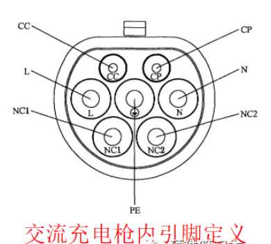
The pin definitions of the AC charging gun are as follows:

Figure 1 AC charging pile charging gun pin definition
L: Output live wire
N: Output neutral line
CC: Connection detection signal, confirming that the connection between the charging pile and the vehicle is normal.
CP: Control guidance signal.
PE: Earth
Regarding CP signals, I think the following points should be emphasized:
① It is the only communication signal between the car charging pile and the charging car. Whether the communication is normal can only be judged by the CP signal.
② The waveform used for communication between the charging pile and the vehicle-mounted OBC is a 1KHz PWM wave. The size of the charging current is determined by the duty cycle. Different duty cycles represent different charging currents. ③ Since the AC neutral and live wires L and N are close to the CP line in the charging gun, and the charging gun is generally 5m long, the interference of the CP line is coupled to the power line through the charging gun, which can easily cause the radiation to exceed the standard. Therefore, it is recommended to replace the CP line with a shielded line (but the shielded line is expensive, and generally the low-frequency conduction without shielding cannot pass).
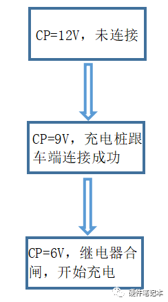
④ Generally, the status of the charging pile can be judged based on the voltage difference between the CP signal and PE.
When the voltage is 12V, it indicates an idle state (not connected).
When the voltage is 9V, it indicates it is connected.
When the voltage is 6V, it indicates that it is in charging state.

Figure 2 Different CP voltages represent connected charging states
This article mainly explains the CP circuit part, how the CP voltage is 12V when idle, 9V when connected, and 6V when charged, how the MCU detects the CP voltage, and then controls the main relay to close or open when a fault occurs.
Previous article:Testing requirements and applications for pure electric drive assembly development
Next article:Parameter matching and simulation design of the powertrain system of a pure electric van logistics vehicle
- Popular Resources
- Popular amplifiers
- Huawei's Strategic Department Director Gai Gang: The cumulative installed base of open source Euler operating system exceeds 10 million sets
- Analysis of the application of several common contact parts in high-voltage connectors of new energy vehicles
- Wiring harness durability test and contact voltage drop test method
- Sn-doped CuO nanostructure-based ethanol gas sensor for real-time drunk driving detection in vehicles
- Design considerations for automotive battery wiring harness
- Do you know all the various motors commonly used in automotive electronics?
- What are the functions of the Internet of Vehicles? What are the uses and benefits of the Internet of Vehicles?
- Power Inverter - A critical safety system for electric vehicles
- Analysis of the information security mechanism of AUTOSAR, the automotive embedded software framework
 Professor at Beihang University, dedicated to promoting microcontrollers and embedded systems for over 20 years.
- Innolux's intelligent steer-by-wire solution makes cars smarter and safer
- 8051 MCU - Parity Check
- How to efficiently balance the sensitivity of tactile sensing interfaces
- What should I do if the servo motor shakes? What causes the servo motor to shake quickly?
- 【Brushless Motor】Analysis of three-phase BLDC motor and sharing of two popular development boards
- Midea Industrial Technology's subsidiaries Clou Electronics and Hekang New Energy jointly appeared at the Munich Battery Energy Storage Exhibition and Solar Energy Exhibition
- Guoxin Sichen | Application of ferroelectric memory PB85RS2MC in power battery management, with a capacity of 2M
- Analysis of common faults of frequency converter
- In a head-on competition with Qualcomm, what kind of cockpit products has Intel come up with?
- Dalian Rongke's all-vanadium liquid flow battery energy storage equipment industrialization project has entered the sprint stage before production
- Allegro MicroSystems Introduces Advanced Magnetic and Inductive Position Sensing Solutions at Electronica 2024
- Car key in the left hand, liveness detection radar in the right hand, UWB is imperative for cars!
- After a decade of rapid development, domestic CIS has entered the market
- Aegis Dagger Battery + Thor EM-i Super Hybrid, Geely New Energy has thrown out two "king bombs"
- A brief discussion on functional safety - fault, error, and failure
- In the smart car 2.0 cycle, these core industry chains are facing major opportunities!
- The United States and Japan are developing new batteries. CATL faces challenges? How should China's new energy battery industry respond?
- Murata launches high-precision 6-axis inertial sensor for automobiles
- Ford patents pre-charge alarm to help save costs and respond to emergencies
- New real-time microcontroller system from Texas Instruments enables smarter processing in automotive and industrial applications
- Half-bridge DC/DC power supply based on LM5036
- July is here, I want to do something, please give me some ideas~~
- How to solve the problem of unstable GND?
- [A goddess who gives a good gift will not run away] Light up my heart
- 24 GHz to 44 GHz Wideband Integrated Upconverter and Downconverter Boosts Microwave Radio Performance While Reducing Size
- The relationship between baud rate and time, and the application of transistor/MOS in communication interface level conversion
- Medium and high voltage GaN devices: vertical or horizontal?
- [Help needed] This is a slightly complicated schematic diagram, about the TI processor and USB power supply part. There are some things I don't understand and I would like to ask everyone for help.
- What is GAN semiconductor technology and how does it work?
- Can the comment statement in C language be written in the IF judgment condition in KEIL5?

 CVPR 2023 Paper Summary: Vision Applications and Systems
 Optimized drivetrain and new semiconductor technologies enable the design of energy-efficient electr


 京公网安备 11010802033920号