A humidifier is a device used to increase the relative humidity in an enclosed area to ensure that there is enough moisture in the area. Especially in winters, when the heater is turned on, it causes the relative humidity of the air to decrease. In this DIY project, we will build an automatic humidifier which can maintain the relative humidity of the atmospheric air through a sensor mechanism. We are also using a display to display the relative humidity (RH) in the form of percentage of moisture in the air. Along with Arduino and LCD, we are also using a DHT11 sensor to read the atmospheric humidity value. If it finds that the relative humidity is below the required limit, it turns on the humidifier and vice versa.
Components Needed to Build a Portable Humidifier
Ultrasonic humidifier
Arduino Nano
5V Relay
7805
25V, 1000uf electrolytic capacitor
12V, 2 AMP AC-DC Adapter
DHT11 Sensor
USB female socket
Performance Board
Connection lines
How Portable Humidifiers Work
A portable humidifier can produce warm/cool mist by using a metal diaphragm that vibrates at high frequencies. The sound vibrations push moisture into the air. The mist produced in the humidifier is absorbed by the air almost instantly. The humidifier needs to float on a bed of water in order to produce mist. The working principle of the humidifier we are going to build can be understood by the block diagram below:

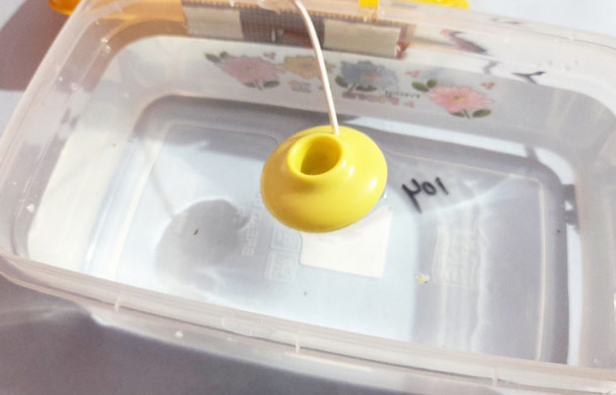
As shown in the block diagram above, the ultrasonic humidifier is placed on the water surface inside the container. The humidifier floats on the water surface. Since we need to sense the humidity, a DHT11 humidity sensor is connected with the Arduino Nano and an OLED display is connected to display the real-time value. Also, based on the humidity value, we need to trigger the relay which in turn switches the humidifier to ON/OFF. Therefore, the humidifier value is compared with the reference value and the humidifier is turned on/off based on the humidity value. The main features of this dehumidifier are as follows:
Type: Floating/Ultrasonic
Power supply: USB, 5V DC
Working current: 500Ma
Noise level: ≤36db
Portable humidifier circuit diagram
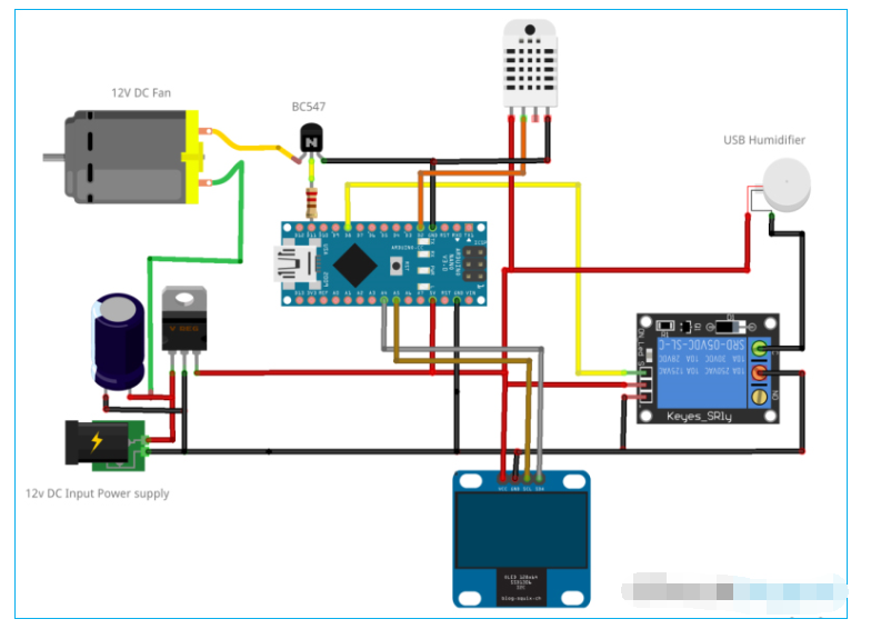
The complete schematics for building a DIY humidifier using Arduino are given here:

Let's understand the circuit diagram in detail. As shown in the diagram, the 12V DC power is first converted to 5V DC power using 7805 regulator and capacitor filter. This power is then provided to the Arduino Nano, OLED, DHT11 and relay circuit. The data pin of DHT11 is connected to the digital input pin of Arduino as shown and configured in the code. The OLED display is connected to the Arduino through the I2C pins i.e. A4, A5 pins of Arduino. Similarly, the digital output pin of Arduino is connected to the Relay and BJT for DC fan drive.
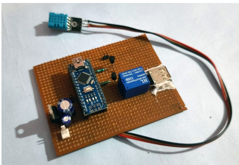
Solder components on the Perfboard:
To make the project setup mobile and more compatible, I soldered all the components on a perfboard as shown below:

Programming the Humidifier with Arduino Nano
After completing the hardware connections successfully as per the circuit diagram, now it is time to flash the code into Arduino. The complete code is given at the end of the document. Here we explain the entire code line by line.
So, the first step is to include the entire required libraries in your code, i.e., “SoftwareSerial.h”, “wire.h”, “Adafruit_SH1106.h” and “DHT.h” in this project. “SoftwareSerial.h” and “wire.h” are in-built, “Adafruit_SH1106.h” can be downloaded from this link and “DHT.h” can be downloaded from this link.
#include
#include
#include
#include "DHT.h"
Then, define the OLED I2C address, which can be OX3C or OX3D, in my case it is OX3C. Usually, the address of a 1.3" OLED is OX3C. Also, the reset pin of the display must be defined. In my case it is defined as -1 because the display shares the reset pin of the Arduino.
#define OLED_ADDRESS 0x3C
#define OLED_RESET -1
Adafruit_SH1106 display(OLED_RESET);
Now, an object is declared in the DHT class type, which can be used throughout the code.
DHT dht;
International humidity = 0;
In setup(), we know that we need to initialize the serial communication, OLED display initialization, etc. Here, for software serial communication, the default baud rate is defined as 9600. Here SH1106_SWITCHCAPVCC is used to power from 3.3V internally and display.begin function is used to initialize the display.
void setup()
{
Serial.Start(9600);
dht.setup(2);
pinMode(6, OUTPUT);
pinMode(11, OUTPUT);
display.begin(SH1106_SWITCHCAPVCC, OLED_ADDRESS);
display.clearDisplay();
}
To read the humidity value from the sensor, use the getHumidity() function and store it in a variable. Then display it on the OLED using the corresponding functions for selecting the text size and cursor position as shown below.
delay(dht.getMinimumSamplingPeriod());
humidity = dht.getHumidity();
display.setTextSize(1);
display.setTextColor(white);
display.setCursor(27, 2);
display.print("Circuit Abstract");
display.setTextSize(1);
display.setCursor(35, 20);
display.print("Humidity(%)");
display.show();
display.setTextSize(2);
display.setCursor(55, 40);
display.print(humidity);
display.show();
delay(50);
display.clearDisplay();
Finally, to trigger the humidifier, the humidity value is compared with the reference humidity level, and if it falls below the reference humidity level, the relay is triggered, turning on the humidifier and the fan.
If (humidity < 88)
{
digitalWrite(6,HIGH);
digitalWrite(11,HIGH);
}
else
{
digitalWrite(6,LOW);
digitalWrite(11,LOW);
}
}
Testing a Portable Humidifier
Once the code and hardware are ready, we can test the performance of the humidifier in a closed room. To do this, follow these steps:
Fill the container no more than 3/4 full with fresh water and float the humidifier on the container as shown below:
Turn on the adapter power to turn on the circuit, and we should now see the humidity level on the OLED.
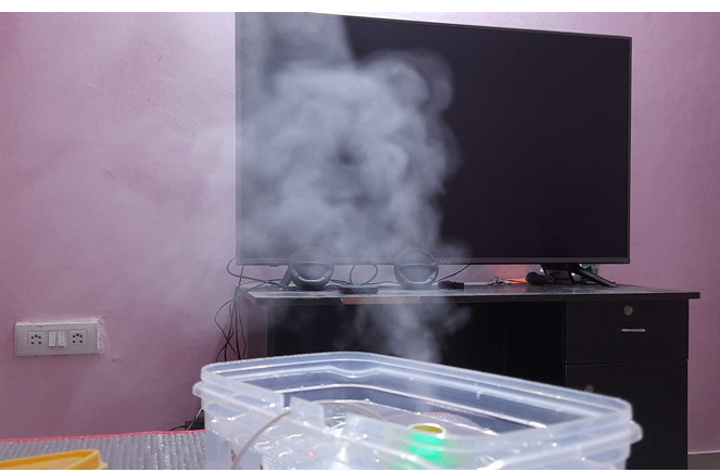
Then, if the humidity level falls below the reference value, the humidifier should start producing mist and the fan should be turned on.
The complete working principle of this homemade humidifier is also explained in the video given at the end of the document. If you have any questions, you can leave them in the comment section below.
Code
#include "SoftwareSerial.h"
#include 《Wire.h》
#include "Adafruit_SH1106.h"
#define OLED_ADDRESS 0x3C
#define OLED_RESET -1
Adafruit_SH1106 display(OLED_RESET);
#include "DHT.h"
DHT dht;
International humidity = 0;
void setup()
{
Sequence.Start(9600);
dht.setup(2);
pinMode(6, OUTPUT);
pinMode(11, OUTPUT);
display.begin(SH1106_SWITCHCAPVCC, OLED_ADDRESS);
display.clearDisplay();
}
void loop()
{
delay(dht.getMinimumSamplingPeriod());
Humidity = dht.getHumidity();
display.setTextSize(1);
display.setTextColor(white);
display.setCursor(27, 2);
display.print("Circuit Digest");
display.setTextSize(1);
display.setCursor(35, 20);
display.print("Humidity (%)");
display.show();
display.setTextSize(2);
display.setCursor(55, 40);
display.print(humidity);
display.show();
delay(50);
display.clearDisplay();
If (humidity <85)
{
digitalWrite(6,HIGH);
digitalWrite(11,HIGH);
}
else
{
digitalWrite(6,LOW);
digitalWrite(11,LOW);
}
}
Previous article:How to Make a Touch Capacitive Piano Using Arduino
Next article:Hi3531DV200's excellent performance in video encoding and decoding
Recommended ReadingLatest update time:2024-11-16 23:48


- Huawei's Strategic Department Director Gai Gang: The cumulative installed base of open source Euler operating system exceeds 10 million sets
- Analysis of the application of several common contact parts in high-voltage connectors of new energy vehicles
- Wiring harness durability test and contact voltage drop test method
- Sn-doped CuO nanostructure-based ethanol gas sensor for real-time drunk driving detection in vehicles
- Design considerations for automotive battery wiring harness
- Do you know all the various motors commonly used in automotive electronics?
- What are the functions of the Internet of Vehicles? What are the uses and benefits of the Internet of Vehicles?
- Power Inverter - A critical safety system for electric vehicles
- Analysis of the information security mechanism of AUTOSAR, the automotive embedded software framework
 Professor at Beihang University, dedicated to promoting microcontrollers and embedded systems for over 20 years.
- Innolux's intelligent steer-by-wire solution makes cars smarter and safer
- 8051 MCU - Parity Check
- How to efficiently balance the sensitivity of tactile sensing interfaces
- What should I do if the servo motor shakes? What causes the servo motor to shake quickly?
- 【Brushless Motor】Analysis of three-phase BLDC motor and sharing of two popular development boards
- Midea Industrial Technology's subsidiaries Clou Electronics and Hekang New Energy jointly appeared at the Munich Battery Energy Storage Exhibition and Solar Energy Exhibition
- Guoxin Sichen | Application of ferroelectric memory PB85RS2MC in power battery management, with a capacity of 2M
- Analysis of common faults of frequency converter
- In a head-on competition with Qualcomm, what kind of cockpit products has Intel come up with?
- Dalian Rongke's all-vanadium liquid flow battery energy storage equipment industrialization project has entered the sprint stage before production
- Allegro MicroSystems Introduces Advanced Magnetic and Inductive Position Sensing Solutions at Electronica 2024
- Car key in the left hand, liveness detection radar in the right hand, UWB is imperative for cars!
- After a decade of rapid development, domestic CIS has entered the market
- Aegis Dagger Battery + Thor EM-i Super Hybrid, Geely New Energy has thrown out two "king bombs"
- A brief discussion on functional safety - fault, error, and failure
- In the smart car 2.0 cycle, these core industry chains are facing major opportunities!
- The United States and Japan are developing new batteries. CATL faces challenges? How should China's new energy battery industry respond?
- Murata launches high-precision 6-axis inertial sensor for automobiles
- Ford patents pre-charge alarm to help save costs and respond to emergencies
- New real-time microcontroller system from Texas Instruments enables smarter processing in automotive and industrial applications
- Ntrip Communication Protocol 1.0
- GaN finishing station 1
- Nuvoton NuMaker-RTU-NUC980 (Chili Board) development board information sharing
- [Perf-V Review] + Perf-V IDE driver and its problems
- Nios 2 software build tools for eclipse freezes when creating a project
- [Qinheng RISC-V core CH582] BUG serial port can only receive up to 8 bytes at a time
- Open Source & Group Purchase: RCSN's Wireless Multi-channel Serial Port Tool is here~
- How to Learn FPGA
- Op amp offset voltage and single or dual power supply issues?
- How to filter out 50HZ power frequency interference introduced by active filtering


 Arduino UNO R4 WiFi Engineering Code
 Workplace Refresher Project Code
 RH37CH


 京公网安备 11010802033920号