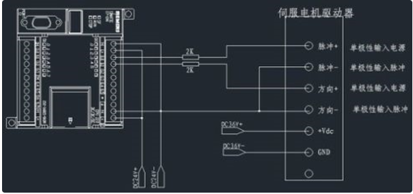
How to connect the servo drive
There are two connections that can be made.
One is the power line, that is, the driver supplies three-phase AC power to the motor, usually with three or four wires;
The second is the encoder signal line, and the position signal is fed back by the encoder to the driver for calculation.
Generally speaking:
Nowadays, most servos are AC servos, so their power cords are no different from those of ordinary three-phase asynchronous motors.
The power cord is connected from the servo drive power module to the motor power port
The encoder is connected from the servo encoder port to the motor encoder port. Depending on the encoder signal, some intermediate conversion devices may need to be installed.

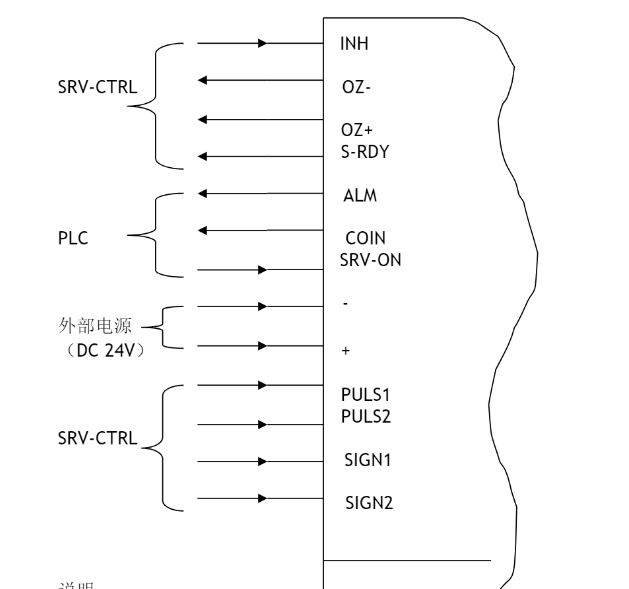
Servo drive external wiring diagram

Note: 1. SRV-CTRL refers to the servo control module of PLC;
2. The one pointed to by → is the input, and the one pointed to by ← is the output.
3. The meanings of each signal are as follows:
INH: prohibit input pulse command (prohibited when open circuit);
OZ-: Z phase output;
OZ+: Z phase output;
S-RDY: The servo drive is ready;
ALM: Servo drive fault alarm;
COIN: Positioning completed;
SRV-ON: Servo drive "on" signal;
COM-: negative pole of power supply;
COM+: positive pole of power supply;
PULS1: command pulse input terminal;
PULS2: command pulse input terminal;
SIGN1: command pulse sign input terminal;
SIGN2: command pulse sign input terminal;
Servo Drive Wiring Guide
In the field of industrial automation, many devices have strict installation specifications. So in order to avoid risks in use and eliminate safety hazards, what are the rules for connecting servo drives?
1. It is recommended to use a three-phase isolation transformer to supply power to reduce the possibility of electric shock.
2. It is recommended that the power supply be powered by a noise filter to improve anti-interference capabilities.
3. Please install a non-fuse short-circuit breaker to cut off the external power supply in time when the drive fails.
4. The grounding wire should be ≥2.5m2, as thick as possible, and made into a single-point grounding. The grounding terminal of the servo motor must be connected to the grounding terminal PE of the driver.
5. Connect the cable shield correctly.
6. To prevent erroneous operation caused by interference, it is recommended to install a noise filter and pay attention to:
(1) The noise filter, servo drive and upper controller should be installed as close as possible.
(2) Surge suppressors must be installed in relays, AC contactors, brakes and other coils.
(3) Power circuit cables and signal lines should not be tied together.
Servo drive failure and repair
The servo drive is a controller used with a servo motor to control the servo motor. It is part of the servo system and plays a very important role in the industrial field. Therefore, after purchasing a servo drive, customers must know some common faults and treatment methods so that they can quickly deal with similar problems. Today, the editor of Huantong Electromechanical will share with you the maintenance methods of the servo drive.
(1) After power is turned on, the LED of the servo driver does not light up
Cause of failure: The voltage may be too low
Solution: Increase the voltage
(2) The LED light is on, but the servo motor does not rotate
Cause of the fault: The command signal is not to the driver signal ground
Solution: Connect the command signal ground to the driver signal ground
(3) The LED light remains red
Cause of failure: There is a fault
Solution: Check whether the machine has problems such as overvoltage, overheating, short circuit, etc.
(4) When the servo motor rotates, the LED light flashes continuously
Cause of failure: Hall phase setting error
Solution: Check whether the motor phase switch setting is correct.
Here is a brief summary of several common servo drive failures and their solutions. Have you learned them? You can easily handle similar problems in the future.
Previous article:What are the advantages of brushless motors? What are the types of brushless motors? How does a brushless motor work?
Next article:Electro-hydraulic servo valve frequency test_Electro-hydraulic servo valve structure diagram
- Huawei's Strategic Department Director Gai Gang: The cumulative installed base of open source Euler operating system exceeds 10 million sets
- Analysis of the application of several common contact parts in high-voltage connectors of new energy vehicles
- Wiring harness durability test and contact voltage drop test method
- Sn-doped CuO nanostructure-based ethanol gas sensor for real-time drunk driving detection in vehicles
- Design considerations for automotive battery wiring harness
- Do you know all the various motors commonly used in automotive electronics?
- What are the functions of the Internet of Vehicles? What are the uses and benefits of the Internet of Vehicles?
- Power Inverter - A critical safety system for electric vehicles
- Analysis of the information security mechanism of AUTOSAR, the automotive embedded software framework
 Professor at Beihang University, dedicated to promoting microcontrollers and embedded systems for over 20 years.
- Innolux's intelligent steer-by-wire solution makes cars smarter and safer
- 8051 MCU - Parity Check
- How to efficiently balance the sensitivity of tactile sensing interfaces
- What should I do if the servo motor shakes? What causes the servo motor to shake quickly?
- 【Brushless Motor】Analysis of three-phase BLDC motor and sharing of two popular development boards
- Midea Industrial Technology's subsidiaries Clou Electronics and Hekang New Energy jointly appeared at the Munich Battery Energy Storage Exhibition and Solar Energy Exhibition
- Guoxin Sichen | Application of ferroelectric memory PB85RS2MC in power battery management, with a capacity of 2M
- Analysis of common faults of frequency converter
- In a head-on competition with Qualcomm, what kind of cockpit products has Intel come up with?
- Dalian Rongke's all-vanadium liquid flow battery energy storage equipment industrialization project has entered the sprint stage before production
- Allegro MicroSystems Introduces Advanced Magnetic and Inductive Position Sensing Solutions at Electronica 2024
- Car key in the left hand, liveness detection radar in the right hand, UWB is imperative for cars!
- After a decade of rapid development, domestic CIS has entered the market
- Aegis Dagger Battery + Thor EM-i Super Hybrid, Geely New Energy has thrown out two "king bombs"
- A brief discussion on functional safety - fault, error, and failure
- In the smart car 2.0 cycle, these core industry chains are facing major opportunities!
- The United States and Japan are developing new batteries. CATL faces challenges? How should China's new energy battery industry respond?
- Murata launches high-precision 6-axis inertial sensor for automobiles
- Ford patents pre-charge alarm to help save costs and respond to emergencies
- New real-time microcontroller system from Texas Instruments enables smarter processing in automotive and industrial applications
- HuaDa HC32F460 series MCU internal FLASH made into USB flash drive
- PCB wiring and layout and circuit design 268 design specifications
- [ESK32-360 Review] + Construction of development environment
- Several circuit designs that must be understood by microcontrollers
- Share an article I read about PLL integer boundary spurs by IDT (Renesas)
- I can't read the TMP275 temperature sensor. I use the STM32 I/O to simulate IIC. Please help.
- Understanding GaN Device Thermal Analysis
- 5. Control objects in previous “Control” competitions
- Album of previous competition questions of the National Undergraduate Electronic Design Competition
- Explanation of the schematic diagram of the xenon lamp flash circuit

 Cadence System-Level Package Design (Wang Hui)
 Cadence System-in-Package Design Allegro SiPAPD Design Guide


 京公网安备 11010802033920号