The development of smart grids has put forward higher requirements for the intelligence of low-voltage electrical appliances. At present, the intelligent stability of small circuit breakers, which are widely used in China, is not enough. The signal acquisition circuit, action execution and intelligent release are all installed in the body. The electromagnetic interference and high temperature generated by the strong electric field in the switch reduce the reliability of the circuit breaker. The intelligent controller introduced in this article is separated from the circuit breaker body and can be connected to multiple circuit breakers to realize the monitoring of multiple circuit breakers.
1 Overall structure of the controller
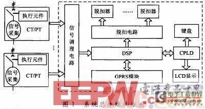
The core of the group intelligent controller uses DSP chip, supplemented by CPLD EPM3128 chip to realize the timing logic of keyboard and LCD, reduce the volume problem caused by the expansion chip, and the peripheral circuit mainly includes signal conditioning circuit and trip control circuit, etc. In order to adapt to the wireless communication of smart grid, GPRS module is added to the intelligent controller, so that the circuit breaker can be better integrated into the smart grid.
2 Controller Hardware Design
The voltage, current and other signals of multiple circuit breakers collected are sent to the DSP processor after conditioning by the signal conditioning circuit. After signal conversion, calculation and judgment, the circuit breaker is tripped through the tripping circuit when there is a fault. The overall structure of the system is shown in Figure 1.
2.1 Signal conditioning circuit module design
The main functions of the signal conditioning module are: first, low-pass filtering to filter out high-frequency noise; second, signal amplification. Due to the large detection current range, in order to adapt to the larger dynamic range, improve the A/D sampling resolution, and make the converted digital signal reflect the size of the analog signal as accurately as possible, two amplification links are designed. One has a larger amplification factor to amplify the signal when the current is small; the other has a smaller amplification factor to amplify the signal when the current is large. Because the signal input range of the A/D converter is limited, in order to prevent the generation of excessively high input voltage when the current signal is large, which may damage the detection circuit and the A/D converter, a level limiting protection circuit is designed.
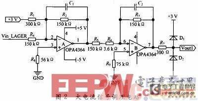
Figure 2 shows the filtering, shifting, amplifying and limiting circuits for each phase of large current signals. Since the input voltage range of the A/D converter is 0 to 3 V, and the input signal is an alternating sine wave with a DC offset level of 0 V, a level shift circuit is designed to raise the current signal. The low-pass filter and signal amplification are composed of two stages of operational amplifiers.
2.2 Tripping circuit module design
The tripping circuit is divided into digital tripping and analog tripping. The digital tripping circuit is relatively simple. The DSP outputs the tripping signal through the I/O port, and drives the flux coil through the optocoupler isolation amplification. The analog tripping circuit is implemented by a comparator level detection circuit. Two comparators are used for each phase current. When the microprocessor does not send a tripping signal and the amplitude of the current signal is within the reference voltage range, the comparator outputs a high level in parallel, otherwise it is a low level. The low-level signal passes through the pulse width detection circuit for anti-interference processing. If the low pulse maintains a certain width, the monostable trigger is triggered, and a pulse of a certain width is output through the drive circuit to open the flux converter, thereby disconnecting the circuit breaker. The analog tripping circuit is shown in Figure 3.
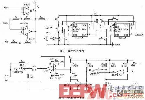
In practical applications, due to the presence of interference, some unnecessary narrow pulses will appear in the output of the comparator level detection circuit. Therefore, a pulse width detection circuit is designed to filter out the interference spikes that cause false triggering of the tripping action. During the design, when the input pulse width is greater than 1ms, a 32.9ms tripping signal is output; when it is less than 1ms, no tripping signal is output.
In practical applications, the short-circuit current at the initial stage of power-on only works within 100 ms. After that, the DSP starts to operate normally after initialization. The analog tripping circuit judges the extremely large short-circuit current. The current setting values are different in the two different situations. Therefore, a switchable reference voltage, namely the MCR disconnection and connection circuit, is designed. At the initial stage of power-on, the voltage across C408 is low, and the comparator outputs a high level, so that T401 is saturated and turned on. Therefore, the reference voltage is reduced, that is, the analog tripping action value is low. When a short-circuit fault occurs, the MCR tripping is realized. After the power-on is stable, the voltage across C408 increases, and the comparator outputs a low level, so that T401 is cut off. At this time, the reference voltage is high. When an extremely large short-circuit current occurs, the analog tripping is realized. The MCR tripping circuit is shown in Figure 4.
2.3 GPRS communication module and DSP hardware interface design
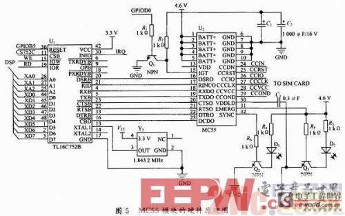
The GPRS communication module uses the MC55GPRS module of SIEMENS. The software schematic diagram is shown in Figure 5. The DSP chip F2812 is extended with a B chip with dual asynchronous serial port (UART) through the external bus interface XINTF, and connected to the MC55 GPRS module. The DSP chip mainly implements the protocols required by the entire system, the collection of monitoring data, and the analysis of the commands of the central master station; the GPRS module completes the wireless communication function.
3 Controller Software Design
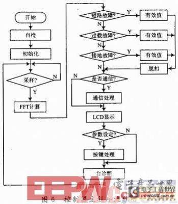
The system software mainly completes functions such as signal sampling, tripping algorithm, communication processing and key display. The software design of the controller uses a mixed programming method of assembly language and C language to optimize the program structure to ensure real-time performance. The program has the characteristics of modularization and subroutine, and anti-interference processing is added to the program design. The main program flow chart is shown in Figure 6.
4 Conclusion
This paper describes in detail the design process of each component of the intelligent controller system and gives a specific circuit diagram. The software and hardware system tests show that the intelligent controller can well complete the signal acquisition, wireless communication and line on/off control functions. In subsequent research, the embedded real-time multi-task operating system μC/OS-Ⅱ can be used as the system software platform to realize the transplantation of μC/OS-Ⅱ on F2812.
Previous article:A high-speed communication interface design based on DSP and FPGA
Next article:Design of a video intelligent analysis system based on DM8168
Recommended ReadingLatest update time:2024-11-16 15:54


- Popular Resources
- Popular amplifiers
-
 MATLAB and FPGA implementation of wireless communication
 -
 Modern arc welding power supply and its control
 -
 Intelligent Control Technology of Permanent Magnet Synchronous Motor (Written by Wang Jun)
 -
 Learn CPLD and Verilog HDL programming technology from scratch_Let beginners easily learn CPLD system design technology through practical methods
- Huawei's Strategic Department Director Gai Gang: The cumulative installed base of open source Euler operating system exceeds 10 million sets
- Analysis of the application of several common contact parts in high-voltage connectors of new energy vehicles
- Wiring harness durability test and contact voltage drop test method
- Sn-doped CuO nanostructure-based ethanol gas sensor for real-time drunk driving detection in vehicles
- Design considerations for automotive battery wiring harness
- Do you know all the various motors commonly used in automotive electronics?
- What are the functions of the Internet of Vehicles? What are the uses and benefits of the Internet of Vehicles?
- Power Inverter - A critical safety system for electric vehicles
- Analysis of the information security mechanism of AUTOSAR, the automotive embedded software framework
 Professor at Beihang University, dedicated to promoting microcontrollers and embedded systems for over 20 years.
- Innolux's intelligent steer-by-wire solution makes cars smarter and safer
- 8051 MCU - Parity Check
- How to efficiently balance the sensitivity of tactile sensing interfaces
- What should I do if the servo motor shakes? What causes the servo motor to shake quickly?
- 【Brushless Motor】Analysis of three-phase BLDC motor and sharing of two popular development boards
- Midea Industrial Technology's subsidiaries Clou Electronics and Hekang New Energy jointly appeared at the Munich Battery Energy Storage Exhibition and Solar Energy Exhibition
- Guoxin Sichen | Application of ferroelectric memory PB85RS2MC in power battery management, with a capacity of 2M
- Analysis of common faults of frequency converter
- In a head-on competition with Qualcomm, what kind of cockpit products has Intel come up with?
- Dalian Rongke's all-vanadium liquid flow battery energy storage equipment industrialization project has entered the sprint stage before production
- Allegro MicroSystems Introduces Advanced Magnetic and Inductive Position Sensing Solutions at Electronica 2024
- Car key in the left hand, liveness detection radar in the right hand, UWB is imperative for cars!
- After a decade of rapid development, domestic CIS has entered the market
- Aegis Dagger Battery + Thor EM-i Super Hybrid, Geely New Energy has thrown out two "king bombs"
- A brief discussion on functional safety - fault, error, and failure
- In the smart car 2.0 cycle, these core industry chains are facing major opportunities!
- The United States and Japan are developing new batteries. CATL faces challenges? How should China's new energy battery industry respond?
- Murata launches high-precision 6-axis inertial sensor for automobiles
- Ford patents pre-charge alarm to help save costs and respond to emergencies
- New real-time microcontroller system from Texas Instruments enables smarter processing in automotive and industrial applications
- Arteli-Migration Manual_SXX32F0xx&GX32F3x0_to_AT32F415_V1.0
- MSP430 MCU Development Record (22)
- Encountered a difficulty, two 8-bit data failed to be spliced into a 16-bit data
- What should I pay attention to when porting the program from STM32L151C8T6 to STM32F103C8T6?
- Is this also called RT-THREAD routine? ??? ???
- Summary of constant current source circuit of op amp
- Award-winning lectures: Nexperia Micro Classroom - GaN application circuit design, PCB layout suggestions and other practical experiences
- Chip Manufacturing 5-Semiconductor Grinding @Packaging Test
- [2022 Digi-Key Innovation Design Competition] Material Unboxing STM32U585AI+ESP32-S3-DEVKITC-1-N8
- 【Chuanglong TL570x-EVM】Review 06 - QT Dome Test

 MATLAB and FPGA implementation of wireless communication


 京公网安备 11010802033920号