As FPGA performance and capacity improve, the use of FPGAs to perform DSP functions is becoming more and more common. In many cases, processors and FPGAs are used together in the same application, using a co-processing architecture to allow the FPGA to perform pre-processing or post-processing operations to speed up processing. This article shows how to use FPGAs and fixed-function DSPs together to design a non-intrusive measurement system based on the principle of Doppler measurement.
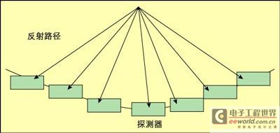
Figure 1: Electron beam focusing technology.

Traditionally, a large number of application designs use specialized digital signal processing (DSP) chips or application-specific standard products (ASSPs) to process digital information through signal processing algorithms. Filtering, video processing, encoding and decoding, and audio processing are just some of the many applications that use DSP.
Today, with the improvement of FPGA performance and capacity, as well as the improvement of efficiency of common arithmetic operations that can be seen in most DSP applications, the practice of using FPGAs to perform DSP functions is becoming more and more common. In many cases, processors and FPGAs are used together in the same application, using a co-processing architecture to let the FPGA perform pre-processing or post-processing operations to speed up processing.
One application that shows this trend is the Doppler measurement system, which can measure the velocity of solids or liquids flowing in various environments. From oil flowing in a pipe to blood flowing in a person's heart, non-invasive measurement methods based on the Doppler measurement principle can greatly reduce risks, reduce costs and improve accuracy compared to previous methods. Generally speaking, these systems are based on DSP technology, combining FPGAs and fixed-function DSP devices such as those provided by TI.
Doppler measurement system
Doppler measurement systems use the Doppler effect to measure the velocity of a moving object (solid, liquid or gas). Probably the most famous application is the radar gun, which is used by traffic patrols to detect speeding cars.
When measuring the motion of something other than the speed of a car, such as the flow of blood through a heart, multiple measurements are needed to determine the details of the more complex flow. One approach is to use electron beam focusing technology.
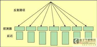
In this technique, a large number of detectors (many small radar guns) are used to measure the frequency return from the transmitting source. The detectors are arranged along a parabola (as shown in Figure 1), so the signal returning from the focal point will arrive at each detector at the same time. By combining these signals and doing a little processing of small fluctuations in apparent velocity, the velocity of the object at the focal point can be determined. This works quite well if the detectors can be moved to scan the entire area of interest, but if this is not possible, another technique can be used that will achieve the same result. By inserting certain programmable delays, changing the time when the inputs from the various detectors are combined, the focal point can be moved to almost any position in the area of interest. For example, adding a certain fixed additional delay will move the focal point farther away, while changing the delay to shorten the propagation path on one side of the detector will move the focal point toward that side.
Figure 2 shows how adjustable delay can be used to create a parabolic effect. Adjustable delay is very easy to implement in register-rich FPGAs and could be a feature that can be stripped out of traditional DSPs as a coprocessor function.
System Implementation Example
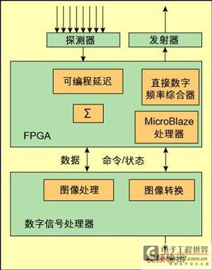
Figure 3 shows a block diagram of an example system implementation. The FPGA in the middle of the figure is responsible for generating the output signal used by the transmitter. This implementation uses the Xilinx Direct Digital Synthesizer IP core, which can easily generate a variety of waveforms. The frequency can be easily changed depending on the measurement goal.
Figure 2: Electron beam focusing technology with delay function.

The detectors measure the analog value of the return signal, producing a digital value that is fed into the FPGA. The FPGA performs some preliminary filtering on the input signal to adjust the position of the detector. The FPGA then inserts a certain programmable delay into each detector data stream to implement the electron beam focusing function. The data streams are combined and a digital filter is responsible for determining the frequency content of the signal. This produces the Doppler reading necessary to determine the focal spot velocity.
There is a MicroBlaze soft core inside the FPGA that controls the measurement process, thereby implementing high-level functions such as scanning, initialization, testing, and diagnosis.
The DSP reads and stores the results of the operations performed by the FPGA. Once a series of scans is completed, the processor can construct a digital image of the scanned area. Different colors can be assigned to different speeds (in linear, logarithmic, or any other scale), and the digital image can be converted into a video image and displayed in real time on a graphics terminal or recorded for later playback. Conversion to JPEG or other video formats can also be easily implemented in the processor using one of the many available software or toolkits, and other system partitions can be experimented with. If real-time video processing and storage consumes too much processor bandwidth, part of the algorithm (such as preprocessing of the scan data) can be performed in the FPGA.
Another important part of the measurement process is determining the mass of the target. This is done by measuring the amount of energy that returns from the focal point to the detector. The more energy that returns, the larger the target (generally speaking). This works particularly well when the target being measured has fixed coherence (such as oil or other liquid flowing in a pipe), but is difficult when there are a variety of different masses or reflections in the system.
Obviously, knowing more about the system under test can provide some clues to the measurement process. Energy measurement can be added to the FPGA coprocessor by storing a digital value corresponding to the amplitude of the returned signal. This value is also delayed by the FPGA.
Alternatively, JPEG processing can be performed as a separate function on the FPGA, leaving the processor more time for data preprocessing. There are many options to choose from, but providing an easy-to-use platform that can quickly implement different segmentations is paramount.
Similar co-processing-oriented applications can benefit from the use of hardware development platforms. Leveraging a hardware platform allows you to easily experiment with various system and algorithm partitions—implementing some functions in the FPGA and others in the DSP. DSP applications are typically difficult to simulate in software, so the ability to quickly create a hardware/firmware/software platform can greatly reduce development time. Using the co-simulation tools in the Xilinx tool suite, developing with The MathWorks Simulink and the target hardware, is a technique that can greatly reduce design time.
Figure 3: Example system block diagram.

Avnet DSP Coprocessor Design Kit
The Avnet DSP Co-Processing Design Kit is designed for a wide range of DSP-oriented applications that require the use of both FPGAs and DSPs. The kit comes with two main boards. The Virtex-4 Evaluation Board (shown in Figure 4) is equipped with a Xilinx Virtex-4 SX-FF668 FPGA, a platform flash configuration PROM, an expansion connector, a Cypress CY7C68013 USB2.0 controller, a National Semiconductor DP83847 10/100 Ethernet port, a 128x64 OSRAM graphics display, 8MB flash, 32MB DDR SDRAM, and various user switches and LEDs. The second board is the TI DSP Adapter Module (shown in Figure 5), which is used to interface between the Virtex-4 board and various TI DSP evaluation boards. The TI board can be purchased from Avnet to complete the development platform.
Previous article:Reliability Design of PCB Board for High-speed DSP System
Next article:Application of DSP system in home appliances
- Huawei's Strategic Department Director Gai Gang: The cumulative installed base of open source Euler operating system exceeds 10 million sets
- Analysis of the application of several common contact parts in high-voltage connectors of new energy vehicles
- Wiring harness durability test and contact voltage drop test method
- Sn-doped CuO nanostructure-based ethanol gas sensor for real-time drunk driving detection in vehicles
- Design considerations for automotive battery wiring harness
- Do you know all the various motors commonly used in automotive electronics?
- What are the functions of the Internet of Vehicles? What are the uses and benefits of the Internet of Vehicles?
- Power Inverter - A critical safety system for electric vehicles
- Analysis of the information security mechanism of AUTOSAR, the automotive embedded software framework
 Professor at Beihang University, dedicated to promoting microcontrollers and embedded systems for over 20 years.
- Innolux's intelligent steer-by-wire solution makes cars smarter and safer
- 8051 MCU - Parity Check
- How to efficiently balance the sensitivity of tactile sensing interfaces
- What should I do if the servo motor shakes? What causes the servo motor to shake quickly?
- 【Brushless Motor】Analysis of three-phase BLDC motor and sharing of two popular development boards
- Midea Industrial Technology's subsidiaries Clou Electronics and Hekang New Energy jointly appeared at the Munich Battery Energy Storage Exhibition and Solar Energy Exhibition
- Guoxin Sichen | Application of ferroelectric memory PB85RS2MC in power battery management, with a capacity of 2M
- Analysis of common faults of frequency converter
- In a head-on competition with Qualcomm, what kind of cockpit products has Intel come up with?
- Dalian Rongke's all-vanadium liquid flow battery energy storage equipment industrialization project has entered the sprint stage before production
- Allegro MicroSystems Introduces Advanced Magnetic and Inductive Position Sensing Solutions at Electronica 2024
- Car key in the left hand, liveness detection radar in the right hand, UWB is imperative for cars!
- After a decade of rapid development, domestic CIS has entered the market
- Aegis Dagger Battery + Thor EM-i Super Hybrid, Geely New Energy has thrown out two "king bombs"
- A brief discussion on functional safety - fault, error, and failure
- In the smart car 2.0 cycle, these core industry chains are facing major opportunities!
- The United States and Japan are developing new batteries. CATL faces challenges? How should China's new energy battery industry respond?
- Murata launches high-precision 6-axis inertial sensor for automobiles
- Ford patents pre-charge alarm to help save costs and respond to emergencies
- New real-time microcontroller system from Texas Instruments enables smarter processing in automotive and industrial applications
- What is the effect of connecting the SW pin of the switching power supply to the capacitor and resistor in series to GND?
- EEWORLD University ----TI LED Driver
- Doorbell program + circuit made by AVR microcontroller timer
- AR1021X series WiFi module selection reference and driver discussion in the field of wireless image transmission
- 2812 TxPR register write failure caused by TxCON highest bit
- Fabrication process of fiber-embedded microfluidic chip
- TMS320F28335 general purpose input/output port GPIO related register introduction
- On-line debugging method for embedded processors
- "Qinheng Evaluation Board Sincerely Send" Activity Q&A Post
- Has anyone used the Raspberry Pi Cm3+?

 Design of vehicle-mounted radar speed measurement system based on DSP


 京公网安备 11010802033920号