Abstract: Finite element technology is used to reduce weight and optimize the structure while considering the collision performance and stiffness characteristics of the vehicle. Considering all harsh working conditions, the optimization function in Altair's product OptiStruct is used to layout and optimize the structure of the vehicle, while achieving the goal of weight reduction.
1 Introduction
Automobile collision is one of the main contents of automobile passive safety research. At present, the commonly used methods in the field of automobile collision research are test methods and computer simulation methods. With the continuous development and promotion of technology, computer simulation technology is more and more widely used in collision analysis and is becoming more and more mature. Since automobile collision analysis is a high-speed and highly nonlinear problem, collision CAE analysis is mainly solved by explicit solvers, such as LS-DYNA, RADIOSS, etc. At present, the more common optimization software is mainly used in the linear field. How to apply optimization technology to collision simulation is a difficult point.
This paper uses Altair's optimization product OptiStruct to perform collision optimization. The complex collision problem is decomposed and sliced, so that linear optimization software can be used to approximate the collision problem across fields and find the optimal solution.
2 Vehicle Collision Optimization Analysis
2.1 Overall collision optimization analysis ideas
As a whole vehicle optimization design, it is necessary to consider the stiffness performance and collision performance of the whole vehicle at the same time, and achieve the lightweight goal and the optimal deformation mode of collision while meeting the stiffness requirements and collision requirements.
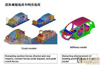
Figure 1 Optimization analysis taking into account both collision analysis and stiffness analysis
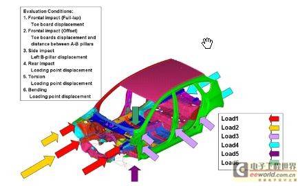
This article only considers the optimization of collision. In terms of collision optimization requirements, the constraints and loads considered in each collision condition are different. Figures 1 and 2 show the loads, constraints, and goals in different collision conditions.
Figure 2 Extraction of collision loads
In the process of finite element analysis, the accuracy of the model and the equivalence of the simplification are of great significance.
Since all collision processes are high-speed and highly nonlinear, to approximate this complex process, many linear slice analyses are required for each collision condition. Because a linear analysis is not enough to simulate the severe plastic deformation during a collision, a series of linear analyses with different boundary conditions can be used to obtain an approximate collision response. This method is called the "moving boundary condition method."
2.2 Introduction to collision optimization analysis methods
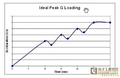
Now, we will take the frontal collision with a rigid barrier with 100% overlap as an example to illustrate the idea and application of the moving boundary condition method. In the frontal collision with a rigid barrier with 100% overlap, if you want to get an excellent collision result, the crushing method of the longitudinal beam, which is the main energy-absorbing component, is the key. We hope to get an ideal step-by-step rising cross-sectional force, and its physical meaning is that the longitudinal beam can be completely crushed step by step. Using the moving boundary condition method, a complex collision process can be divided into several parts, and optimized using Altair's product OptiStruct.
Figure 3 Ideal crushing force of longitudinal beam section
The crushed area of the longitudinal beam is divided into several parts, such as the four parts in Figure 4.
Figure 4 Division of longitudinal beam crushing area
[page]
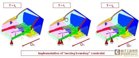
The transient collision event can be approximately sliced into several linear analyses with different boundary conditions. The constraint position is moved to the position closest to the non-deformed area to form the boundary conditions of each linear analysis. The load of each linear optimization analysis is the equivalent vehicle acceleration of the ideal cross-sectional force corresponding to the crushing of the part.
Figure 5 Schematic diagram of moving boundary conditions
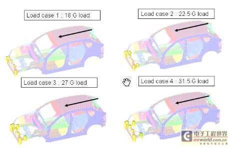
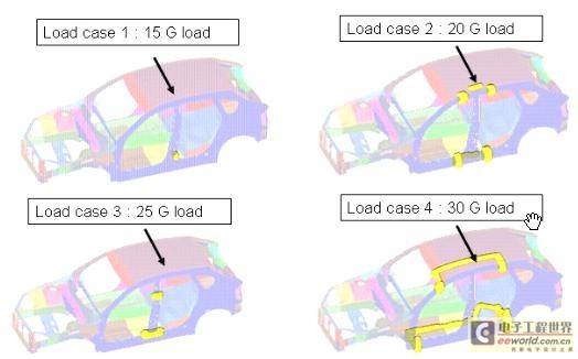
Figure 6 shows the boundary conditions and loads of the four working conditions of the moving boundary condition method. The yellow balls represent the movement of the boundary conditions at different times.
Figure 6 Loads and constraints for four working conditions of the moving boundary method
2.3 Practical Application Results
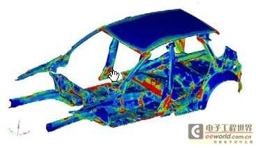
According to the moving boundary condition method, the optimization function of OptiStruct is used to optimize the frontal 100% overlap rigid barrier collision. The material distribution cloud map of the whole vehicle after optimization is shown in Figure 7.
Figure 7 Optimization results (material distribution cloud diagram)
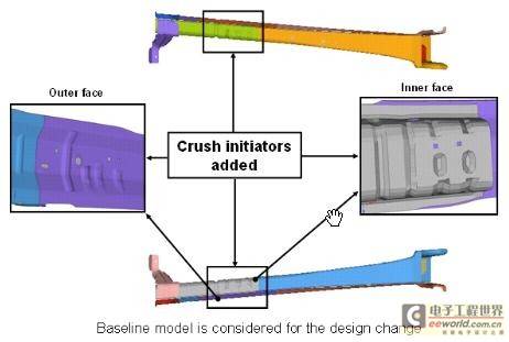
According to the optimized material distribution cloud map, the longitudinal beam is optimized, and the optimization result is shown in Figure 8. With the development of automobile technology, laser welding of the front longitudinal beam is becoming more and more common in some mid-to-high-end cars. This optimization method can obtain the optimal thickness of each part very accurately, achieving particularly good results.
Figure 8 Optimization scheme of longitudinal beam
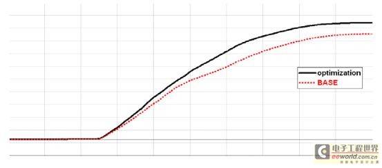
The optimized longitudinal beam was re-calculated for the whole vehicle collision. Figure 9 shows the comparison of the energy absorption results of the longitudinal beam before and after the improvement. The energy absorption of the optimized longitudinal beam is much better than that of the original design.
Figure 9 Comparison of longitudinal beam energy absorption results
[page]
2.4 Application of the moving boundary condition method to other collision conditions
Similarly, the moving boundary condition method can also be applied to other collision analyses. The analysis idea is similar to the frontal 100% overlap rigid barrier collision. Figure 10 shows the boundary conditions and loads of the four working conditions of the moving boundary condition method in the side movable barrier collision. The yellow ball represents the movement of the boundary conditions at different times.
Figure 10 Application of the moving boundary condition method for side impact
3 Conclusion
By using the moving boundary condition method to approximate the simulation of complex collision engineering, we can obtain the optimal material distribution and the most ideal crushing path, and ultimately obtain the best vehicle collision performance.
Taking into account the stiffness and collision requirements of the vehicle, using OptiStruct to optimize the body-in-white as a whole can obtain the optimal material distribution of the vehicle and achieve the goal of lightweighting.
This article illustrates the application of the moving boundary condition method in a 100% overlap frontal rigid barrier collision. The moving boundary condition method can also be applied to 40% offset deformable barrier frontal collision, side movable barrier collision, high-speed rear collision, static top pressure and other working conditions, all of which have achieved significant results.
4 References
[1] Reed. Jaguar Cars Limited. Body and trim CAE. Engineering Centre. Applications of OptiStruct optimization to body in white design.
[2] Axel Schumacher & Michael Seibel. New optimization strategies for crash design.
[3] RJYang. Reliability-Based Multidisciplinary Design Optimization of Vehicle Structures.(end)
Previous article:Analysis of the design and considerations of the passive anti-theft system for automobiles
Next article:Analysis of rear-mounted safety systems for safer travel
- Car key in the left hand, liveness detection radar in the right hand, UWB is imperative for cars!
- After a decade of rapid development, domestic CIS has entered the market
- Aegis Dagger Battery + Thor EM-i Super Hybrid, Geely New Energy has thrown out two "king bombs"
- A brief discussion on functional safety - fault, error, and failure
- In the smart car 2.0 cycle, these core industry chains are facing major opportunities!
- The United States and Japan are developing new batteries. CATL faces challenges? How should China's new energy battery industry respond?
- Murata launches high-precision 6-axis inertial sensor for automobiles
- Ford patents pre-charge alarm to help save costs and respond to emergencies
- New real-time microcontroller system from Texas Instruments enables smarter processing in automotive and industrial applications
- Innolux's intelligent steer-by-wire solution makes cars smarter and safer
- 8051 MCU - Parity Check
- How to efficiently balance the sensitivity of tactile sensing interfaces
- What should I do if the servo motor shakes? What causes the servo motor to shake quickly?
- 【Brushless Motor】Analysis of three-phase BLDC motor and sharing of two popular development boards
- Midea Industrial Technology's subsidiaries Clou Electronics and Hekang New Energy jointly appeared at the Munich Battery Energy Storage Exhibition and Solar Energy Exhibition
- Guoxin Sichen | Application of ferroelectric memory PB85RS2MC in power battery management, with a capacity of 2M
- Analysis of common faults of frequency converter
- In a head-on competition with Qualcomm, what kind of cockpit products has Intel come up with?
- Dalian Rongke's all-vanadium liquid flow battery energy storage equipment industrialization project has entered the sprint stage before production
- Allegro MicroSystems Introduces Advanced Magnetic and Inductive Position Sensing Solutions at Electronica 2024
- Car key in the left hand, liveness detection radar in the right hand, UWB is imperative for cars!
- After a decade of rapid development, domestic CIS has entered the market
- Aegis Dagger Battery + Thor EM-i Super Hybrid, Geely New Energy has thrown out two "king bombs"
- A brief discussion on functional safety - fault, error, and failure
- In the smart car 2.0 cycle, these core industry chains are facing major opportunities!
- The United States and Japan are developing new batteries. CATL faces challenges? How should China's new energy battery industry respond?
- Murata launches high-precision 6-axis inertial sensor for automobiles
- Ford patents pre-charge alarm to help save costs and respond to emergencies
- New real-time microcontroller system from Texas Instruments enables smarter processing in automotive and industrial applications
- Keyence vision camera communicates with Siemens 1500 PLC to achieve grasping correction with the robot
- LSM6DSO(X) sensor driver key code analysis: read_data_polling routine (Part 2)
- Xunwei STM32MP157 development board Linux + MCU learning materials and tutorials summary (manual + video)
- Microchip FAQ | TA100-VAO secure boot and message authentication for CAN FD in ADAS and IVI systems
- C2000 Piccolo MCU F28027F LaunchPad Development Kit
- [MPS Mall Big Offer Experience Season] Unboxing
- [ESP32-Korvo Review] Part 4: Text-to-Speech TTS
- Some unused boards
- 【2022 Digi-Key Innovation Design Competition-Smart Study Room Based on Raspberry Pi
- 【NXP Rapid IoT Review】+ Trial Computer Programming & Mobile Phone Control


 Multimodal perception parameterized decision making for autonomous driving
 CVPR 2023 Paper Summary: Robotics


 京公网安备 11010802033920号