With the promotion of electric vehicles and autonomous driving technology, the use of a large number of electronic and electrical equipment has put forward increasingly stringent requirements for electromagnetic compatibility ( EMC ), and EMC issues in product design have become increasingly important. This paper establishes finite element models for the main circuit in three cases: simple copper plating, adding iron connecting pieces, and adding iron connecting pieces and copper wires. The surface electric field strength is calculated and the electric field distribution trend is analyzed. The electromagnetic field distribution of the fan motor control circuit and the main circuit is measured experimentally.
The experimental results prove the correctness of the simulation results, and then analyze the reasons for the local electric field concentration and provide improvement measures. The signal integrity analysis of the signal network connecting the main chip of the control circuit to the MOSFET gate is carried out, and the line eye diagram is obtained by simulation calculation. By adjusting the terminal resistance , the eye height and eye width of the eye diagram are improved, which effectively improves the signal transmission quality.
Through finite element analysis of the main circuit and signal integrity simulation of the control circuit, the electric field strength and line eye diagram are accurately studied. Compared with the traditional qualitative analysis method, more accurate electronic circuit improvement measures are given.
In recent years, China's automobile industry has developed rapidly. The overall level of automobile design and manufacturing has been greatly improved. At the same time, users' demands for automobile safety, energy saving, environmental protection, comfort and other aspects have also been continuously improved, so on-board electrical and electronic equipment have been widely used. Relevant statistics show that the cost of electronic components in domestic compact cars accounts for about 25% of the whole vehicle, and the proportion of luxury brand cars is as high as 40%. In addition, the types and quantities of these electronic products are constantly increasing, and their operating frequency and power are also gradually increasing.
With the promotion of electric vehicles and autonomous driving technology, electrical and electronic equipment in automobiles are further highly integrated, and product functions are becoming increasingly complex. More electrical and electronic products need to be placed in a limited space, so the electromagnetic environment between electronic products has become more severe, and more stringent requirements have been put forward for the electromagnetic compatibility of electronic products in automobiles. The more prominent electromagnetic compatibility ( EMC ) problems may even cause various faults in the car, such as incorrect operation of indicator lights and failure of airbags to pop out in time.
On May 23, 2018, at a press conference at Mobileye, an autonomous driving technology company owned by Intel, an autonomous car ran through a red light without any signs of braking. The reason was that the wireless signal transmitter of the camera installed in the car by the TV station staff emitted electromagnetic interference, which affected the normal operation of the transponder in the traffic light. Although no casualties were caused, this accident exposed the seriousness of electromagnetic compatibility issues. How to effectively solve the electromagnetic compatibility problem at the device level in automobiles is the top priority of current research work.
Regarding electromagnetic compatibility, reference [7] mainly suppresses electromagnetic radiation on the propagation path through filtering and shielding; reference [8] mainly reasonably arranges the lines on the printed circuit board (PCB) and reduces electromagnetic radiation by reducing the current loop area . In modern electrical and electronic equipment, the continuous increase in signal frequency and the high-speed operation of switching tubes will cause serious electromagnetic interference.
At the same time, due to the skin effect of current, the current density at the edge of the copper plate of the printed circuit board is too large, causing the local near-field strength to be too large. This will inevitably lead to an increase in the far-field radiation capability, causing other sensitive components to be strongly subject to electromagnetic interference. Therefore, reducing the local electric field strength is an important item in electromagnetic compatibility.
Signal Integrity (SI) refers to the integrity of the waveform of a circuit signal when it reaches the receiving port after passing through a transmission path without affecting the quality of other signals in the system. When the signal on the circuit can reach the receiving end from the transmitting end according to the required timing, duration and voltage amplitude, it means that the circuit has good signal integrity.
The signal integrity of the circuit is affected by many factors, generally due to the steep edge of the signal, impedance mismatch and electromagnetic interference from adjacent lines. If every signal network on the circuit board is analyzed during signal integrity analysis, it will inevitably consume a lot of manpower and resources, and the feasibility is low. Therefore, in actual signal integrity analysis, the signals in the system are usually divided and the key signals in the signal network are calculated to save computing time and resources.
For the analysis of signal integrity, the literature [14] uses S parameters to analyze the impedance changes of signal lines at different frequencies, while the eye diagram is a method for analyzing signal quality at a fixed operating frequency. In comparison, the eye diagram can intuitively reflect the system noise, time jitter, overshoot and other phenomena of the signal network at the operating frequency.
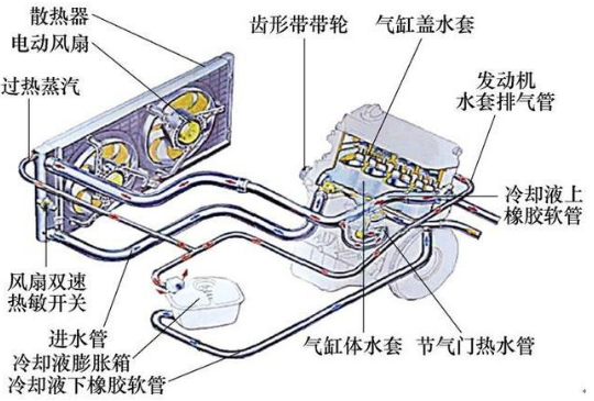
The cooling system of automobile engines generally improves the cooling efficiency of the radiator by increasing the wind speed around the water tank through the radiator fan. The development of the cooling fan has gone through three stages: ① The engine directly drives the fan to rotate, which is inefficient and increases fuel consumption; ② The electromagnetic clutch controls the fan speed, which generally has two or three gears, but because the engine temperature is closely related to the driving environment and driving habits, the clutch needs to be frequently shifted and is easily damaged, and the improvement in efficiency and reduction in fuel consumption are not very obvious; ③ The electronic fan stage, the vehicle electronic control unit (ECU) controls the fan speed, which can achieve stepless speed regulation according to the water tank temperature, high efficiency, low energy consumption, and long life.
This paper analyzes and optimizes the electromagnetic compatibility between the automotive electronic fan motor control circuit and the main circuit, thereby improving the circuit's anti-interference ability in a complex electromagnetic environment and reducing the circuit's external radiation emission.

Automobile cooling device principle


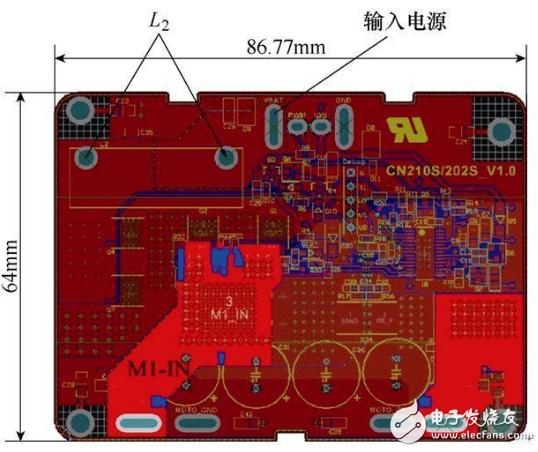
Actual picture and partial enlargement
in conclusion
This paper establishes finite element models for some main circuits in three cases, calculates the surface electric field strength, analyzes the electric field distribution trend, and verifies the correctness of the simulation through experiments. The calculation results show that there will be very high-frequency components at the moment of MOS tube switching on and off. The appearance of 90° right angles causes the signal to radiate the strongest at the right angles, causing serious electromagnetic interference to the surrounding circuits. It is recommended that in high-power circuits, even if the operating frequency is low, 90° right angles should be avoided.
Signal integrity analysis shows that the eye diagram of the driving signal can be significantly improved by adjusting the circuit parameters. Compared with the traditional empirical qualitative analysis method, numerical simulation technology can provide more accurate electronic circuit improvement measures, thereby improving the reliability of PCB and reducing the failure rate.
Previous article:SK Telecom cooperates with Harman and others to realize 5G in-car TV broadcasting
Next article:CISSOID and the Institute of Electrical Engineering of the Chinese Academy of Sciences jointly promote the widespread application of silicon carbide power devices
Recommended ReadingLatest update time:2024-11-17 02:31


- Popular Resources
- Popular amplifiers
- Car key in the left hand, liveness detection radar in the right hand, UWB is imperative for cars!
- After a decade of rapid development, domestic CIS has entered the market
- Aegis Dagger Battery + Thor EM-i Super Hybrid, Geely New Energy has thrown out two "king bombs"
- A brief discussion on functional safety - fault, error, and failure
- In the smart car 2.0 cycle, these core industry chains are facing major opportunities!
- The United States and Japan are developing new batteries. CATL faces challenges? How should China's new energy battery industry respond?
- Murata launches high-precision 6-axis inertial sensor for automobiles
- Ford patents pre-charge alarm to help save costs and respond to emergencies
- New real-time microcontroller system from Texas Instruments enables smarter processing in automotive and industrial applications
- Innolux's intelligent steer-by-wire solution makes cars smarter and safer
- 8051 MCU - Parity Check
- How to efficiently balance the sensitivity of tactile sensing interfaces
- What should I do if the servo motor shakes? What causes the servo motor to shake quickly?
- 【Brushless Motor】Analysis of three-phase BLDC motor and sharing of two popular development boards
- Midea Industrial Technology's subsidiaries Clou Electronics and Hekang New Energy jointly appeared at the Munich Battery Energy Storage Exhibition and Solar Energy Exhibition
- Guoxin Sichen | Application of ferroelectric memory PB85RS2MC in power battery management, with a capacity of 2M
- Analysis of common faults of frequency converter
- In a head-on competition with Qualcomm, what kind of cockpit products has Intel come up with?
- Dalian Rongke's all-vanadium liquid flow battery energy storage equipment industrialization project has entered the sprint stage before production
- Allegro MicroSystems Introduces Advanced Magnetic and Inductive Position Sensing Solutions at Electronica 2024
- Car key in the left hand, liveness detection radar in the right hand, UWB is imperative for cars!
- After a decade of rapid development, domestic CIS has entered the market
- Aegis Dagger Battery + Thor EM-i Super Hybrid, Geely New Energy has thrown out two "king bombs"
- A brief discussion on functional safety - fault, error, and failure
- In the smart car 2.0 cycle, these core industry chains are facing major opportunities!
- Rambus Launches Industry's First HBM 4 Controller IP: What Are the Technical Details Behind It?
- The United States and Japan are developing new batteries. CATL faces challenges? How should China's new energy battery industry respond?
- Murata launches high-precision 6-axis inertial sensor for automobiles
- Ford patents pre-charge alarm to help save costs and respond to emergencies
- Request a cadencePCB file
- MSP-FET430UIF Win8 Driver
- National College Student Electronic Design Competition TI Processor Board Application Details
- Finally I've waited for you, all the terminal R&D and testing data has been collected!
- Application of Lock-in Amplifier in TDLAS Technology
- Addressing the challenges of diverse multi-standard wireless communication devices in the connected home
- [RVB2601 Creative Application Development] Chapter 7: Using lvgl and solving the problem of insufficient SRAM memory
- Domestic operating systems are on the rise. Is this Linux your cup of tea?
- The difference between polymer tantalum capacitors and ordinary tantalum capacitors
- GD32L233 GCC startup file and link file sharing

 Electromagnetic compatibility testing technology and application (Edited by Wu Dongyan, Chen Xiaolei, Hang Haimei, etc.)


 京公网安备 11010802033920号