1. Project introduction
Topic selection guidance, project sharing: Lighter-z/embedded base
1.1 System composition
This design consists of STC89C52 microcontroller circuit + ADXL345 acceleration sensor circuit + button circuit + buzzer alarm circuit + DS18B20 temperature sensor circuit + LED light circuit + GSM module circuit + power supply circuit.
1.2 System functions
1. When the board is placed vertically, the buzzer will not sound the alarm. If the board is tilted to a certain angle, the buzzer will sound the alarm. If the correct status is not returned for about 15 seconds, GSM sends an alarm message to the mobile phone: Help me!!.
2. If the temperature exceeds 38 degrees, the buzzer will alarm and the temperature will continue to be too high for about 15 seconds. At the same time, a text message will alarm: has a cold
3. It is designed with a false alarm button. When the buzzer alarms, if the elderly thinks it is a false alarm, then the button will be pressed and the buzzer will stop alarming. If the problem persists, the alarm will still be issued.
4. There are indicator lights showing the SMS processing process.
5. The GSM module is SIM800A. This module is fully compatible with the circuit program of SIM900A and has the same appearance.
2. Partial circuit design
2.1 GSM SIM800A module circuit design
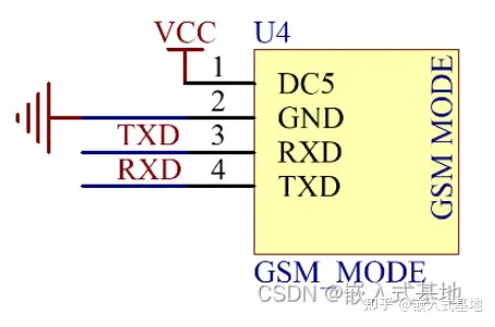
The GSM module is a functional module that integrates GSM radio frequency chip, baseband processing chip, memory, power amplifier device, etc. on a circuit board. It has an independent operating system, GSM radio frequency processing, baseband processing, and provides standard interfaces. The GSM module has all the basic functions of sending SMS text messages, voice calls, GPRS data transmission and other communication based on GSM network. Simply put, the GSM module plus keyboard, display and battery is a mobile phone.
Module application areas: remote monitoring, remote smart meter reading, smart home and vehicle-mounted equipment and other remote communication equipment.
The module interface schematic diagram is shown below:

The specific schematic diagram inside the module is shown below:

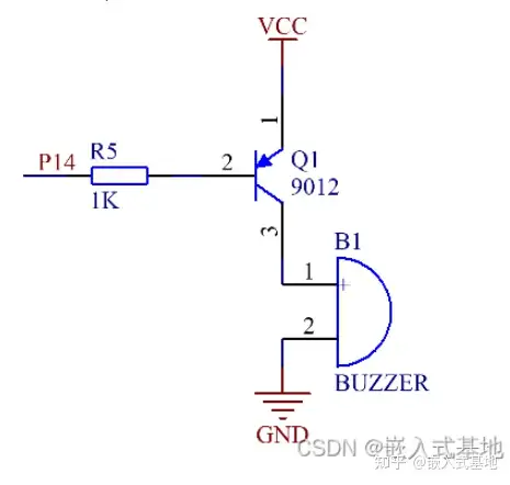
2.2 Design of buzzer alarm circuit (active low level)
The circuit is driven by a transistor 9012. As long as the microcontroller control pin is low, the buzzer will sound an alarm, otherwise it will not sound. The buzzer's sound mode can be controlled by controlling the square wave output of the microcontroller pin.

2.3 ADXL345 tilt sensor module circuit design
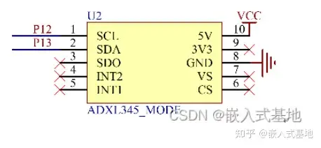
This design chooses the inclination sensor ADXL345 module to detect relevant status information in real time. The ADXL345 is a small, thin, ultra-low power 3-axis accelerometer with high resolution (13 bits) and a measurement range of ±16g. Digital output data is in 16-bit two's complement format and can be accessed via the SPI (3-wire or 4-wire) or I2C digital interface.
The ADXL345 module interface diagram is shown below:

2.4 DS18B20 temperature sensor module circuit design
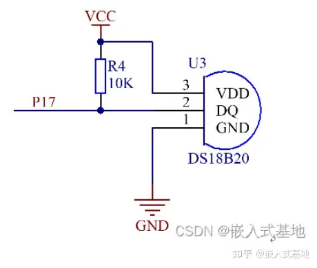
DS18B20 is a commonly used digital temperature sensor. It outputs a digital signal and has the characteristics of small size, low hardware overhead, strong anti-interference ability and high precision.
The DS18B20 interface diagram is shown below:

3. Partial code display
3.1 ds18b20 initialization
bit Init_DS18B20(void)
{
bit dat=0;
DQ = 1; //DQ reset
DelayUs2x(5); //Slight delay
DQ = 0; //The microcontroller pulls DQ low
DelayUs2x(200); //The exact delay is greater than 480us and less than 960us
DelayUs2x(200);
DQ = 1; //pull the bus high
DelayUs2x(50); //Receive presence pulse of 60-240us after 15~60us
dat=DQ; //If x=0, the initialization is successful, if x=1, the initialization fails
DelayUs2x(25); //Return with a slight delay
return dat;
}
3.1 ADXL345 initialization
void Init_ADXL345()
{
Single_Write_ADXL345(0x31,0x0B); //Measurement range, plus or minus 16g, 13-bit mode
Single_Write_ADXL345(0x2C,0x08); //The rate is set to 12.5
Single_Write_ADXL345(0x2D,0x08); //Select power mode
Single_Write_ADXL345(0x2E,0x80); //Enable DATA_READY interrupt
Single_Write_ADXL345(0x1E,0x00); //X offset is written according to the status of the test sensor
Single_Write_ADXL345(0x1F,0x00); //Y offset is written according to the status of the test sensor
Single_Write_ADXL345(0x20,0x05); //Z offset is written according to the status of the test sensor
}
Previous article:Design of LED Chinese character dot matrix scrolling display based on AT89C51 microcontroller
Next article:Based on 51 microcontroller wireless Bluetooth APP control LED light brightness design
Recommended ReadingLatest update time:2024-11-16 13:32


 Professor at Beihang University, dedicated to promoting microcontrollers and embedded systems for over 20 years.
- Innolux's intelligent steer-by-wire solution makes cars smarter and safer
- 8051 MCU - Parity Check
- How to efficiently balance the sensitivity of tactile sensing interfaces
- What should I do if the servo motor shakes? What causes the servo motor to shake quickly?
- 【Brushless Motor】Analysis of three-phase BLDC motor and sharing of two popular development boards
- Midea Industrial Technology's subsidiaries Clou Electronics and Hekang New Energy jointly appeared at the Munich Battery Energy Storage Exhibition and Solar Energy Exhibition
- Guoxin Sichen | Application of ferroelectric memory PB85RS2MC in power battery management, with a capacity of 2M
- Analysis of common faults of frequency converter
- In a head-on competition with Qualcomm, what kind of cockpit products has Intel come up with?
- Dalian Rongke's all-vanadium liquid flow battery energy storage equipment industrialization project has entered the sprint stage before production
- Allegro MicroSystems Introduces Advanced Magnetic and Inductive Position Sensing Solutions at Electronica 2024
- Car key in the left hand, liveness detection radar in the right hand, UWB is imperative for cars!
- After a decade of rapid development, domestic CIS has entered the market
- Aegis Dagger Battery + Thor EM-i Super Hybrid, Geely New Energy has thrown out two "king bombs"
- A brief discussion on functional safety - fault, error, and failure
- In the smart car 2.0 cycle, these core industry chains are facing major opportunities!
- The United States and Japan are developing new batteries. CATL faces challenges? How should China's new energy battery industry respond?
- Murata launches high-precision 6-axis inertial sensor for automobiles
- Ford patents pre-charge alarm to help save costs and respond to emergencies
- New real-time microcontroller system from Texas Instruments enables smarter processing in automotive and industrial applications
- Share a PD fast charging power deception chip CH224 is very practical
- Alloy sampling resistor series
- TI's Class AB car amplifier chip recommendations
- I am majoring in measurement and control, and am planning to work in the embedded system industry. Could you please tell me if this is the right major for me?
- MSP432E401Y MCU intelligent car speed measurement function
- Motor drive video
- Complementary PWM generation and dead zone control module of c2000
- About nRF52xx ADC stability issues
- Guys, please help me, I've been stuck for 3 days and can't figure it out
- Zero Knowledge Open Source Sharing-Zero Knowledge ESP8266 Development Board Released

 Easy to get started with mobile communications


 京公网安备 11010802033920号