For components like this that contain chips, the most important thing is to learn how to understand the pin functions of the chip, rather than to memorize the statements of the chip. The same components from different manufacturers have slight differences, so when purchasing such things, ask the manufacturer for a chip manual and design the program or circuit according to the manual.
1602 LCD
1602: 16 means that 16 characters can be displayed in one line, and 02 means there are two lines in total
Only numbers and characters can be displayed
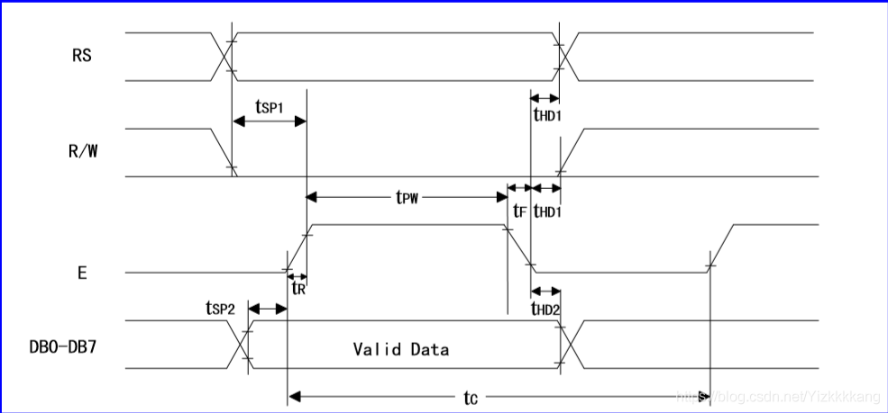
Write data timing diagram


RS low level selects data, high level selects instruction
RW High level means read, low level means write
E is the enable signal, which sends high and low pulses
According to the timing diagram, write the instruction (data) first, delay, and give the pulse
Write command (data)
First select the write instruction, then assign the value to port P0, and then write the program according to the instructions of the timing diagram. Writing data is the same, so I won't go into details.
void write_com(uchar com) //
{
lcdrs=0; // set write com
P0=com; // give value data
delay(5);
lcden=1;// Âö³å
delay(5);
lcden=0;
}
Initialization Procedure


What is displayed here is the RAM address of each bit of the matrix, only 00-0F, 40-4F are displayed. Although there are addresses on the right side of these two rows, they are not displayed. They can be used to shift the full screen to the left to achieve a dynamic effect.
void init()
{
dula=0; //Because the digital tube will divide the voltage, turn it off to prevent insufficient voltage
wela=0;
lcden=0;
write_com(0x38); //Initialize 5*7 matrix
//0000 1DCB D displays C cursor B flashes
write_com(0x0f);
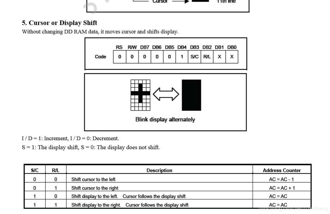
//0000 01NS
write_com(0x06); //The cursor moves, but the data does not move
write_com(0x80); //Initialize pointer position, 80H is the first position
}
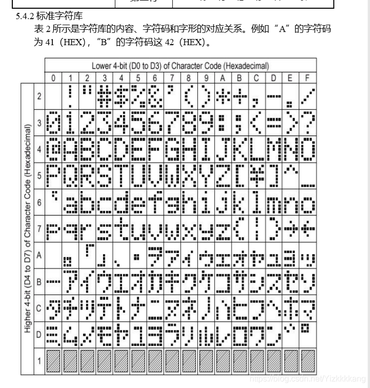
Character Manual
We can write data using matrices, according to the following table

If you want to write directly, separate them with '
write_data('A');
If you want to write a string of characters
Just use the matrix
uchar code table[]=" I Love U";
But here the matrix is no longer surrounded by {} curly braces, but double quotes.
move

According to the chip manual, assigning P0 = 0x18 means moving left once, and the cursor will also move left.
other settings

0x01 is to clear the screen 0x02 is to enter
Code Sample
Does not include movement, includes clearing the screen, and code examples on a new page
#include #define uchar unsigned char #define uint unsigned int sbit lcden=P3^4; sbit lcdrs=P3^5; sbit dula=P2^6; sbit wela=P2^7; uchar code table[]=" I Love U"; uchar code table1[]=" FOREVER"; uchar code table2[]="Just a joking"; void delay(uint z) { uint x,y; for(x=z;x>0;x--) for(y=110;y>0;y--); } void write_com(uchar com) //write instruction { lcdrs=0; // set writing com P0=com; // input value data delay(5); lcden=1; // give pulse delay(5); lcden=0; } void write_data(uchar date) //write data { lcdrs=1; //Select data P0=date; delay(5); lcden=1; delay(5); lcden=0; } void init() { dula=0; wela=0; lcden=0; write_com(0x38); write_com(0x0f); write_com(0x06); write_com(0x80); } void main() { uint time; init(); for(time=0;time<12;time++) { write_data(table[time]); delay(300); } write_com(0x80+0x40); for(time=0;time<11;time++) { write_data(table1[time]); delay(300); } delay(300); write_com(1); delay(300); delay(300); delay(300); write_com(0x80+0x00); for(time=0;time<13;time++) { write_data(table2[time]); delay(300); } while(1); } Full screen mobile code #include #define uchar unsigned char #define uint unsigned int sbit lcden=P3^4; sbit lcdrs=P3^5; sbit dula=P2^6; sbit wela=P2^7; uchar code table[]="I Love U"; uchar code table1[]="FOREVER"; uchar code table2[]="Just a joking"; void delay(uint z) { uint x,y; for(x=z;x>0;x--) for(y=110;y>0;y--); } void write_com(uchar com) //дÃüÁî { lcdrs=0; // set write com P0=com; // give value data delay(5); lcden=1;// Âö³å delay(5); lcden=0; } void write_data(uchar date) // { lcdrs=1; // set write com P0=date; // give value data delay(5); lcden=1;// Âö³å delay(5); lcden=0; } void init() { dula=0; wela=0; lcden=0; write_com(0x38); write_com(0x0f); write_com(0x06); write_com(0x80+0x10); void main() { uint time; init(); for(time=0;time<8;time++) { write_data(table[time]); delay(20); } write_com(0x80+0x50);//»»ÐÐ for(time=0;time<7;time++) { write_data(table1[time]); delay(20); } for(time=0;time<16;time++) { write_com(0x18); delay(200); } while(1); }
Previous article:Step-by-step teaching of 51 MCU Lesson 7 | AT24C02 I²C bus data transmission
Next article:Hands-on teaching of 51 single-chip microcomputer | Section 4 Dynamic digital tube, use 6-bit digital tube to make a clock
- Popular Resources
- Popular amplifiers
- Naxin Micro and Xinxian jointly launched the NS800RT series of real-time control MCUs
- How to learn embedded systems based on ARM platform
- Summary of jffs2_scan_eraseblock issues
- Application of SPCOMM Control in Serial Communication of Delphi7.0
- Using TComm component to realize serial communication in Delphi environment
- Bar chart code for embedded development practices
- Embedded Development Learning (10)
- Embedded Development Learning (8)
- Embedded Development Learning (6)
 Professor at Beihang University, dedicated to promoting microcontrollers and embedded systems for over 20 years.
- Intel promotes AI with multi-dimensional efforts in technology, application, and ecology
- ChinaJoy Qualcomm Snapdragon Theme Pavilion takes you to experience the new changes in digital entertainment in the 5G era
- Infineon's latest generation IGBT technology platform enables precise control of speed and position
- Two test methods for LED lighting life
- Don't Let Lightning Induced Surges Scare You
- Application of brushless motor controller ML4425/4426
- Easy identification of LED power supply quality
- World's first integrated photovoltaic solar system completed in Israel
- Sliding window mean filter for avr microcontroller AD conversion
- What does call mean in the detailed explanation of ABB robot programming instructions?
- Europe's three largest chip giants re-examine their supply chains
- Breaking through the intelligent competition, Changan Automobile opens the "God's perspective"
- The world's first fully digital chassis, looking forward to the debut of the U7 PHEV and EV versions
- Design of automotive LIN communication simulator based on Renesas MCU
- When will solid-state batteries become popular?
- Adding solid-state batteries, CATL wants to continue to be the "King of Ning"
- The agency predicts that my country's public electric vehicle charging piles will reach 3.6 million this year, accounting for nearly 70% of the world
- U.S. senators urge NHTSA to issue new vehicle safety rules
- Giants step up investment, accelerating the application of solid-state batteries
- Guangzhou Auto Show: End-to-end competition accelerates, autonomous driving fully impacts luxury...
- ROM, RAM, SRAM, DRAM, RRAM, FRAM, flash, there are so many types, how to distinguish them
- Novice Question
- How to install tens of billions of transistors into a chip?
- Milliohm meter-host computer design based on [EVAL-ADICUP360]
- PCB Design Software Bluetooth Speaker Practice│PCB Layout and Module Capture
- Allwinner V853 heterogeneous AI intelligent vision development board review - Solution to the problem of constant restart and reflashing of firmware
- 25 "Million Miles" Raspberry Pi Car - Nam Wheel Control
- Is it better to settle a head injury privately or publicly?
- STM32 SWD can only be downloaded once
- What should I do if the hand-soldered components are magnetic?

 TLV2464ID


 京公网安备 11010802033920号