This paper introduces a scheme that uses a single-chip microcomputer as a controller to control the steam pressure and furnace wall temperature in a closed container under the state of gas-liquid mixture. The controller adopts fuzzy control technology and is suitable for nonlinear, time-varying and time-delay systems. Experimental results show that it has the characteristics of no overshoot, no static error and strong robustness.
1. Hardware composition of the system
The overall hardware structure is shown in Figure 1.

The PIC16C74 microcontroller is selected as the main control chip, which has 40 pins, an oscillation frequency of up to 20MHz, 4KB of program memory and 192Bytes of RAM. It has 3 built-in timers, 2 * modules, a synchronous serial communication interface, a 5-input channel 8-bit A/D conversion module, and provides 12 interrupt sources.
1.2 Temperature measurement circuit part
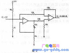
The temperature sensing element of this circuit uses a resistance temperature detector (RTD). The resistance value RT and temperature T have the following corresponding relationship: RT=R0(1+AT+BT2-100CT3+CT4) where: R0 is the resistance value at 0℃, and A, B, and C are all constants. Honeywell's HEL-700 platinum RTDs are used in this system.
The circuit design is shown in Figure 2. V0 is the output voltage, and RT is the resistance at temperature T. Then: V0=[(1+RT/1000)-1]*10/10=0.001RT. According to the voltage value output by the circuit in Figure 2 and the above formula, the RT value at this time is calculated, and the temperature value at the measuring point is obtained through the known resistance/temperature relationship of the RTD. It is also possible to achieve a one-to-one correspondence between the output voltage value and the temperature value at the measuring point by connecting a differential input proportional operation circuit after the output voltage V0. After that, it can be directly connected to an analog input of the microcontroller.
1.3 Pressure measurement circuit part
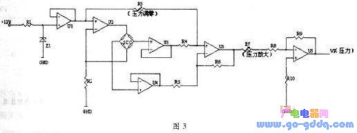
The circuit of the pressure measurement part is shown in Figure 3. The pressure sensor used in this system is the SCC series product of Honeywell . The pressure sensor plays the role of a Wheatstone bridge and can provide a stable temperature output when driven by a constant current source. In Figure 3, the circuit in front of the SCC provides a constant current source; in the circuit behind, U3, U4, U5, and U6 are all integrated operational amplifiers. Using U3 and U4 as followers can play an isolation role to prevent the signal in the rear circuit from affecting the front circuit. R3 is a potentiometer. Adjusting it can calibrate the bias of the pressure sensor, and adjusting R7 can change the amplification factor of the voltage output by the pressure sensor.
1.4 Heating circuit
The heating component of this system uses a heating wire, and the change of heating power is achieved by controlling the on and off of the thyristor. Figure 4 is a bidirectional thyristor type trigger circuit.
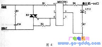
MOC3021 is a bidirectional thyristor output type photocoupler, which is used to isolate the microcontroller system and trigger the external bidirectional thyristor. When the microcontroller outputs a high level , there is current input to the input end of MOC3021 , the bidirectional thyristor at the output end is turned on, and the external bidirectional thyristor KS is triggered to turn on. The time of outputting a high level is the width of the trigger pulse.
This system achieves high-temperature and high-pressure steam by heating the furnace wall. This process is a nonlinear and time-varying process, so fuzzy control technology is used to control this system.
In order to overcome the shortcomings of large amount of calculation and time consumption, fuzzy controller is implemented by table lookup method in practical application.
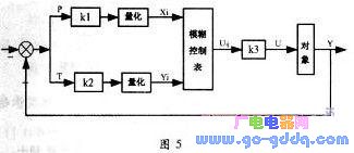
The specific method is: first, a fuzzy control table is obtained through offline calculation, and then the control index is stored in the computer memory. In the control process, the pressure deviation value Pi and the temperature deviation value Ti are obtained according to the sampling, and they are multiplied by the quantization factors k1 and k2 respectively, and the domains Xi and Yj are obtained after quantization, and the control quantity Uij, which is also expressed in the form of the domain, is found from the Ith row and the Jth column of the control table, and the control quantity U is multiplied by the corresponding proportional factor k3 to obtain the control quantity U, which can be used for the controlled process to achieve the expected control purpose. The system structure composed of this fuzzy controller is shown in Figure 5.
The key to fuzzy controller design is to obtain the fuzzy control table. The specific design method is as follows:
(1) Input and output variables of fuzzy controller
The deviation T between the actual temperature and the given temperature and the deviation P between the actual pressure and the given pressure are determined as input variables, and the time when an I/O port of the microcontroller that controls the current of the heating device outputs a high level in a single sampling cycle is used as the output variable. The fuzzy controller designed in this way has two inputs and one output.
(2) Determine the range of input and output and the domain elements and quantization factors of the corresponding language variables. The actual range of input and output of the system, P, T, and U, is set according to the actual situation of the system. The element integer domain and its range can be set as needed. In this system, since overshoot of temperature and pressure is not allowed, and the temperature value is always changing in the direction close to the set value, T and P are both negative values. Therefore, the element integer domain range of P and T can be set as follows:

(3) Conversion from exact quantity to element integer domain
According to the obtained precise values of temperature deviation T and pressure deviation P, they are multiplied by corresponding quantization factors k1 and k2 respectively, and corresponded to integer points on the element integer domain.
(4) Establishment of fuzzy control rule table
There are many ways to determine fuzzy control rules: 1) Generate rules based on expert experience or process control knowledge; 2) Generate control rules based on the fuzzy model of the process; 3) Generate control rules based on systematic observation and measurement of manual control operations; 4) Generate control rules based on learning algorithms. In this system, fuzzy control rules are established based on expert experience.
(5) Precision of fuzzy quantity
The output obtained by the fuzzy control rule table is a fuzzy quantity. It must be refined before it can be used to control the object. This process is called refinement, also known as defuzzification or fuzzy judgment. Commonly used methods include the centroid method, the median method, and the maximum membership method. In this system, the maximum membership method is used for fuzzy judgment.
Finally, a query table can be created, and the output control quantity can be directly obtained by querying this table according to the quantized pressure deviation value and temperature deviation value. The table is stored in the RAM of the microcontroller , and the table is directly queried during program operation to obtain Uij, and then the heater conduction time in a single sampling cycle is obtained through defuzzification, thereby realizing the control of the heating amount.
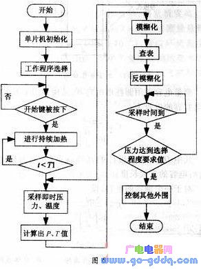
There are two work processes to choose from in this system, one is 1.2×10⁵Pa (corresponding to steam temperature 121℃), and the other is 2.0×10⁵Pa (corresponding to steam temperature 134℃). The temperature sensing element RTD is placed at a certain position on the outer wall of the container. During the heating process, the wall temperature should be limited to below a certain temperature T1, because the heat radiation generated by excessively high wall temperature will have a greater impact on the sterilized items in the container.
At the beginning of the working process, the program only controls the temperature. As long as the wall temperature does not exceed a certain set temperature, the heating element will heat at maximum power. When the temperature exceeds the set temperature, it will enter the fuzzy control stage.
The initialization of the microcontroller mainly includes the input and output settings of the I/O port, the selection of the analog input channel and the selection of the timer.
The program flow is shown in Figure 6.
Previous article:Implementation of intelligent control of aromatherapy beauty steam bath room based on PIC16F877
Next article:Application of PIC16LF874 microcontroller in capacitance measurement module
 Professor at Beihang University, dedicated to promoting microcontrollers and embedded systems for over 20 years.
- Innolux's intelligent steer-by-wire solution makes cars smarter and safer
- 8051 MCU - Parity Check
- How to efficiently balance the sensitivity of tactile sensing interfaces
- What should I do if the servo motor shakes? What causes the servo motor to shake quickly?
- 【Brushless Motor】Analysis of three-phase BLDC motor and sharing of two popular development boards
- Midea Industrial Technology's subsidiaries Clou Electronics and Hekang New Energy jointly appeared at the Munich Battery Energy Storage Exhibition and Solar Energy Exhibition
- Guoxin Sichen | Application of ferroelectric memory PB85RS2MC in power battery management, with a capacity of 2M
- Analysis of common faults of frequency converter
- In a head-on competition with Qualcomm, what kind of cockpit products has Intel come up with?
- Dalian Rongke's all-vanadium liquid flow battery energy storage equipment industrialization project has entered the sprint stage before production
- Allegro MicroSystems Introduces Advanced Magnetic and Inductive Position Sensing Solutions at Electronica 2024
- Car key in the left hand, liveness detection radar in the right hand, UWB is imperative for cars!
- After a decade of rapid development, domestic CIS has entered the market
- Aegis Dagger Battery + Thor EM-i Super Hybrid, Geely New Energy has thrown out two "king bombs"
- A brief discussion on functional safety - fault, error, and failure
- In the smart car 2.0 cycle, these core industry chains are facing major opportunities!
- The United States and Japan are developing new batteries. CATL faces challenges? How should China's new energy battery industry respond?
- Murata launches high-precision 6-axis inertial sensor for automobiles
- Ford patents pre-charge alarm to help save costs and respond to emergencies
- New real-time microcontroller system from Texas Instruments enables smarter processing in automotive and industrial applications
- bluenrg-2 cannot connect to other devices directly when it is the host
- Playing with Zynq Serial 43——[ex62] Image Laplace Edge Extraction of OV5640 Camera
- [NXP Rapid IoT Review] + First try of mobile APP
- CC2541 Key Fob Reference Design
- Give feedback on Lingdong Micro's MM32F013x library functions and routines
- Design of wireless voice communication system based on Mesh technology
- [Domestic RISC-V Linux Board Fang·Starlight VisionFive Trial Report] Environment Preparation——Install MySQL
- Project Management (Passive Components)
- Could you please tell me what is the name of the plastic film wrapped around the outside of the transformer?
- About the power supply of the circuit board

 Design paper of dot matrix electronic display screen
 *** *** *** *** *** *** ***** ** Two wire/I2C Bus READ/WRITE Sample Routines of Microchip s ** 2
 ICL8212CPA


 京公网安备 11010802033920号