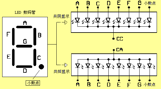
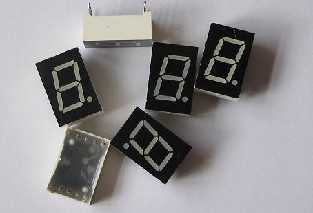
The usage of digital tubes is no different from that of light-emitting diodes. It is just that seven or eight light-emitting diodes are combined on a module to form an 8-shaped figure and a decimal point to display numbers. In order to reduce the number of pins, the same poles of each light-emitting tube are connected together as a common point, thus giving rise to the concept of common anode and common cathode digital tubes. Common anode tubes are to connect the positive poles of each light-emitting tube together, while common cathode tubes are just the opposite. See the figure below:
void main(void)
{
P2=0xff; //Turn off the segment code first
P3=0xff; //Turn off the bit code
TMOD=0x01; //Set T0 to mode 1
TH0=0xf8; //Load the initial count high bit
TL0=0x30; //Load the initial count low bit
EA=1; //Total charge allowed
ET0=1; //T0 charge allowed
fg=1; //Set the on and off flags to on
TR0=1; //Start interrupt
while(1);
}
Reference address:Manufacturing and driving of digital tube circuit

Generally speaking, the absorption current of most logic ICs is stronger than the output current. Therefore, everyone likes to use common cathode digital tubes because there are more ICs to choose from. Unfortunately, my set of digital tubes is common anode, so I plan to use a three-stage tube to drive the common end.

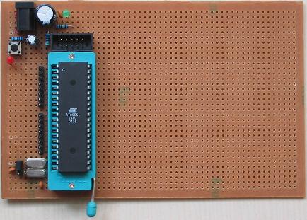
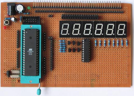
My minimal system board:

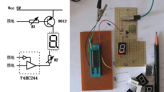
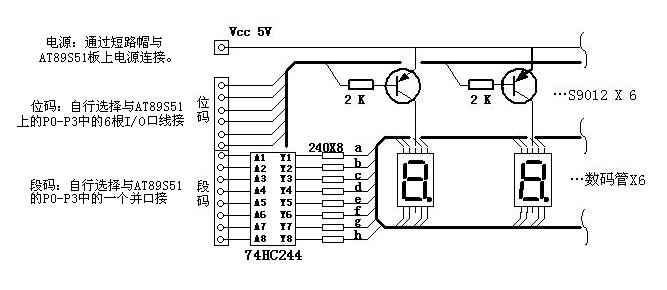
I used the most commonly used S9012. First, I had to plan the circuit method, so I used the most commonly used dynamic scanning display. First, I built the simplest circuit and debugged the parameters of the components to be used.

Do not connect R2 and 74HC244 in the figure above, and directly ground one segment of the digital tube. Adjust R1, and when the base current of S9012 is measured to be 0.21mA, the collector, that is, the digital tube, has 40mA, indicating that the amplification factor is sufficient. At this time, connect R2 and 74HC244, and adjust R2 to control the current of the digital tube at 15mA. In this way, when the 8 segments are lit together, a current of 120mA must pass through the transistor. The base needs 0.63mA. In order to reduce the load of the transistor, the transistor should be oversaturated. Adjust R1 to make the base current 2mA. At this time, the voltage between the collector and the drain is measured to be about 0.1V. Good! At this time, R1 is 2K. R2 is 240 ohms. OK.

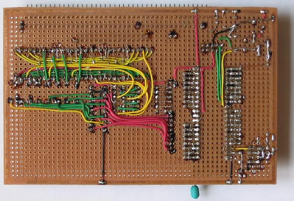
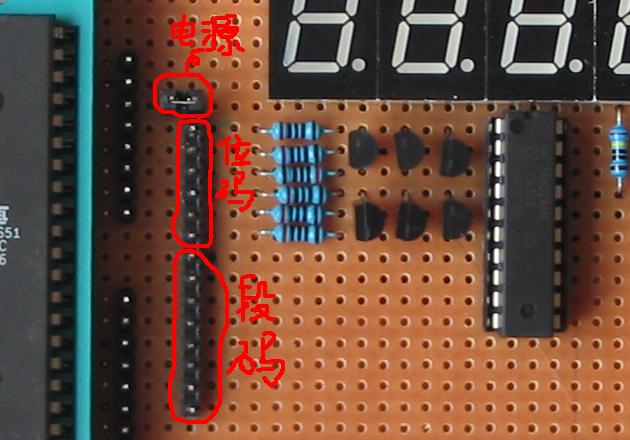
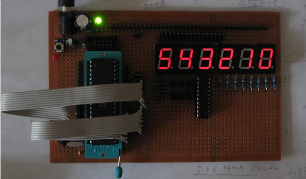
The next step is to determine the circuit. There are three groups of interfaces between the circuit interface and AT89S51: segment code, bit code and power supply. In order to make AT89S51 independent, these three levels of interfaces are all made of pins, and are freely connected to the P1-P3 ports of AT89S51 with flat cables. The power supply is connected with a short-circuit cap. The completed board is shown in the figure below.

Reverse:

illustrate:

Then it’s time to write the program. Let's write a query method first!
//The six-digit code tube is flashing at an interval of 0.3 seconds. This is a query method, which takes up more CPU resources
/************************************************************************
Define pins: P2_0-------upper horizontal a P3_0-------ones
P2_1-----upper right vertical b P3_1-------ten
P2_2-----lower right vertical c P3_2-------hundreds
P2_3-----lower horizontal d P3_3-------thousands
P2_4-----lower left vertical e P3_4-------ten thousand
P2_5-----upper left vertical f P3_5-------hundred thousand
P2_6-----middle horizontal g
P2_7-----decimal point H
**********************************************************************/
# include
typedef unsigned char uchar;
ucharcode bit_num[]={0xfe,0xfd,0xfb,0xf7,0xef,0xdf};//bit code value table: 0,1,2,3,4,5
ucharcode meg_val[]={0x03,0x9f,0x25,0x0d,0x99,0x49};//segment code value table: 0,1,2,3,4,5
uchar codehello[]={0x03,0xe3,0xe3,0x61,0x91,0xff}; //HELLO
ucharcode beybey[]={0x89,0x61,0xc1,0x89,0x61,0xc1};//beybey
ucharcode ab6789[]={0xc1,0x11,0x09,0x01,0x1f,0x41};//ab6789
void delay(int n);
void main(void)
{
uchar i,m;
P2=0xff; //Turn off the segment code first
P3=0xff; //Turn off the bit code
delay(20);//Wait for a
whilewhile(1)
{
for (m=30;m>0;m--) //Display 30 times, about 0.3 seconds
{
for(i=0;i<=5;i++)
{
P2=0xff;
P3=bit_num[i]; //Output bit code to P3 port
P2=ab6789[i]; //Output segment code to P2 port
delay(5);
}
}
P2=0xff; //Turn off segment code
P3=0xff; //Turn off bit code
delay(1000); //Wait for 0.3 seconds
}
}
//The six-digit code tube is flashing at an interval of 0.3 seconds. This is a query method, which takes up more CPU resources
/************************************************************************
Define pins: P2_0-------upper horizontal a P3_0-------ones
P2_1-----upper right vertical b P3_1-------ten
P2_2-----lower right vertical c P3_2-------hundreds
P2_3-----lower horizontal d P3_3-------thousands
P2_4-----lower left vertical e P3_4-------ten thousand
P2_5-----upper left vertical f P3_5-------hundred thousand
P2_6-----middle horizontal g
P2_7-----decimal point H
**********************************************************************/
# include
typedef unsigned char uchar;
uchar
uchar
uchar code
uchar
uchar
void delay(int n);
void main(void)
{
uchar i,m;
P2=0xff; //Turn off the segment code first
P3=0xff; //Turn off the bit code
delay(20);//Wait for a
whilewhile(1)
{
for (m=30;m>0;m--) //Display 30 times, about 0.3 seconds
{
for(i=0;i<=5;i++)
{
P2=0xff;
P3=bit_num[i]; //Output bit code to P3 port
P2=ab6789[i]; //Output segment code to P2 port
delay(5);
}
}
P2=0xff; //Turn off segment code
P3=0xff; //Turn off bit code
delay(1000); //Wait for 0.3 seconds
}
}
void delay(int n) //Subroutine
{
int j;
uchar k;
for(j=0;j
for(k=255;k>0;k--);
}
}
=========================================
When I write the program into the chip and plug it in to run, it is garbled. Guess what happened?
It turns out that the direction of the P2 port is reversed. Have you noticed that in the AT89S51 pin arrangement, P0--P1 and P3 are all PX_0 on the top. Only the P2 port pin arrangement is P2_0 on the bottom. The direction is reversed. Since it is reversed, I will rewrite the segment code table. Try again, everything is normal.
Here I will talk about the arrangement of the segment codes. Many people asked how the digital tube segment codes are arranged. I also checked online, and it seems that there is no standard arrangement. It depends on your own connection method. This is also the reason why some digital tube programs downloaded from the Internet cannot be displayed normally on your own board. Generally speaking, the top diagram has the most marking methods. In the above program, it was originally intended that P2_0 corresponded to segment code a (that is, the horizontal line above). Until P2_7 corresponds to segment h (that is, the decimal point). As a result, who knew that the P2 port was just reversed. In this way, it is reversed, and P2_0 corresponds to segment h (the decimal point). For example, the segment code of the digital tube I originally defined to display "2" is 10100100B. Once it is connected in reverse, it is no longer "2". If you want to display "2" again, you have to reverse the high and low bits of the segment code. Change it to 00100101B and it will be OK.

Let's write another one that uses interrupts to display:
//This is an interrupt mode, and it also flashes.
/************************************************************************
Define pins: P2_0------decimal point P3_0------units
P2_1------middle horizontal P3_1------tens
P2_2------upper left vertical P3_2------hundreds
P2_3------lower left vertical P3_3------thousands
P2_4------lower horizontal P3_4------ten thousand
P2_5------lower right vertical P3_5------hundred thousand
P2_6------upper right vertical
P2_7------upper horizontal
******************************************************************/
# include
typedef unsigned char uchar;
ucharcode bit_num[]={0xfe,0xfd,0xfb,0xf7,0xef,0xdf}; //bit code: 0,1,2,3,4,5
uchar codemeg_val[]={0x49,0x99,0x0d,0x25,0x9f,0x03}; //segment code: 0,1,2,3,4,5
uchar i,aa; //define global variable
bit fg; //define a light on and off flag
/************************************************************************
Define pins: P2_0------decimal point P3_0------units
P2_1------middle horizontal P3_1------tens
P2_2------upper left vertical P3_2------hundreds
P2_3------lower left vertical P3_3------thousands
P2_4------lower horizontal P3_4------ten thousand
P2_5------lower right vertical P3_5------hundred thousand
P2_6------upper right vertical
P2_7------upper horizontal
******************************************************************/
# include
typedef unsigned char uchar;
uchar
uchar code
uchar i,aa; //define global variable
bit fg; //define a light on and off flag
void timer0(void) interrupt 1 using 1 //interrupt program
{
if (fg) //When fg is 1, light up the 6-digit digital tube
{ P2=0xff;
if (i>=6)
{
i=0;
}
else
{
P3=bit_num[i]; //Output bit code to P3 port
P2=meg_val[i]; //Output segment code to P2 port
i++;
}
}
else //When fg is 0, turn off the digital tube
{
if(aa==0)
{
P3=0xff;
P2=0xff;
}
}
aa++;
if (aa>=254) //When the aa value accumulates to 254, the fg flag flips.
{
fg=~fg;
aa=0;
}
TH0=0xf8; //Reinstall the initial value of the timer, 2ms, the value is 65536-2000
TL0=0x30;
}
{
if (fg) //When fg is 1, light up the 6-digit digital tube
{ P2=0xff;
if (i>=6)
{
i=0;
}
else
{
P3=bit_num[i]; //Output bit code to P3 port
P2=meg_val[i]; //Output segment code to P2 port
i++;
}
}
else //When fg is 0, turn off the digital tube
{
if(aa==0)
{
P3=0xff;
P2=0xff;
}
}
aa++;
if (aa>=254) //When the aa value accumulates to 254, the fg flag flips.
{
fg=~fg;
aa=0;
}
TH0=0xf8; //Reinstall the initial value of the timer, 2ms, the value is 65536-2000
TL0=0x30;
}
void main(void)
{
P2=0xff; //Turn off the segment code first
P3=0xff; //Turn off the bit code
TMOD=0x01; //Set T0 to mode 1
TH0=0xf8; //Load the initial count high bit
TL0=0x30; //Load the initial count low bit
EA=1; //Total charge allowed
ET0=1; //T0 charge allowed
fg=1; //Set the on and off flags to on
TR0=1; //Start interrupt
while(1);
}
OK!
Previous article:Production of AT89S51ISP Download Cable
Next article:Homemade MCU Part 5 (1) ... LCD1602 Driver
Recommended Content
Latest Microcontroller Articles
He Limin Column
Microcontroller and Embedded Systems Bible
 Professor at Beihang University, dedicated to promoting microcontrollers and embedded systems for over 20 years.
MoreSelected Circuit Diagrams
MorePopular Articles
- Innolux's intelligent steer-by-wire solution makes cars smarter and safer
- 8051 MCU - Parity Check
- How to efficiently balance the sensitivity of tactile sensing interfaces
- What should I do if the servo motor shakes? What causes the servo motor to shake quickly?
- 【Brushless Motor】Analysis of three-phase BLDC motor and sharing of two popular development boards
- Midea Industrial Technology's subsidiaries Clou Electronics and Hekang New Energy jointly appeared at the Munich Battery Energy Storage Exhibition and Solar Energy Exhibition
- Guoxin Sichen | Application of ferroelectric memory PB85RS2MC in power battery management, with a capacity of 2M
- Analysis of common faults of frequency converter
- In a head-on competition with Qualcomm, what kind of cockpit products has Intel come up with?
- Dalian Rongke's all-vanadium liquid flow battery energy storage equipment industrialization project has entered the sprint stage before production
MoreDaily News
- Allegro MicroSystems Introduces Advanced Magnetic and Inductive Position Sensing Solutions at Electronica 2024
- Car key in the left hand, liveness detection radar in the right hand, UWB is imperative for cars!
- After a decade of rapid development, domestic CIS has entered the market
- Aegis Dagger Battery + Thor EM-i Super Hybrid, Geely New Energy has thrown out two "king bombs"
- A brief discussion on functional safety - fault, error, and failure
- In the smart car 2.0 cycle, these core industry chains are facing major opportunities!
- The United States and Japan are developing new batteries. CATL faces challenges? How should China's new energy battery industry respond?
- Murata launches high-precision 6-axis inertial sensor for automobiles
- Ford patents pre-charge alarm to help save costs and respond to emergencies
- New real-time microcontroller system from Texas Instruments enables smarter processing in automotive and industrial applications
Guess you like
- Disassembling Panasonic's antique tape recorder and analyzing its circuit design 50 years ago
- [Senior Science] What is an RF power amplifier? What are its applications?
- Release several sets of millimeter wave radar modules
- DSP clock and timer general timer
- Custom MMIC Blog: From Mixers to Phased Array Radar
- Answer the questions to win prizes | Shijian Exploration: Smoke detection empowers smart buildings
- Todd Gillenwater talks about why he is optimistic about UWB technology
- Embedded Linux boutique resources, with source code comments
- Does anyone have the component library and PCB package library of POWER PCB 5.0? Please share
- Looking to buy C8051F video?

 Design of digital static magnetic parameter measurement system
 MSC1208 pdf datasheet


 京公网安备 11010802033920号